LiftMaster LA412UL Installation Blueprint - Page 2
Standard Dual Gate Installation, Operator Dimensions, Non-contact Sensors, Contact Sensors Edge
 |
View all LiftMaster LA412UL manuals
Add to My Manuals
Save this manual to your list of manuals |
Page 2 highlights
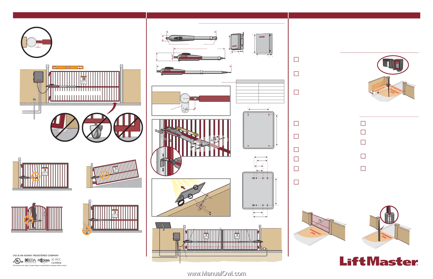
GATE CONSTRUCTION & SITE PREPARATION There should only be a maximum of 4" (10.2 cm) from the center of the hinge to the edge of the post or column. If the distance is greater than 4" (10.2 cm) entrapment protection for this area is required. Maximum gate weight/length: 850 lbs. (385.6 kg) / 10 ft (3.0 m) 750 lbs. (340.2 kg) / 12 ft (3.7 m) 650 lbs. (294.8 kg) / 14 ft (4.3 m) 550 lbs. (249.5 kg) / 16 ft (4.9 m) Gate MUST swing freely and be supported entirely by its hinges. Gate MUST be level. Gate and gate post MUST be plumb. Warning Placard on both sides of gate. High and Low Voltage UL approved conduit. Power and control wiring MUST be run in separate conduits Earth Ground Rod Check national and local codes for proper depth Gate MUST NOT hit or drag across ground. Remove ANY/ALL wheels from the bottom of gate. Gate MUST have a smooth bottom edge, no protrusions should exist. ! DO NOT weld the crossbar on just a few pickets, or they could bend. DO NOT install on uphill or downhill gates. ! DO NOT install on ANY pedestrian passageways, doorways, or gates. DO NOT install next to sprinklers or any area that may expose the bottom of operator to water. INSTALLATION OVERVIEW OPERATOR DIMENSIONS Weight: 13.2 lbs. (6 kg.) 36-5/16" (92.2 cm) 4" (10.2 cm) 4-1/2" (11.4 cm) 1/2" DIA. (1.3 cm DIA.) 1/4" (0.64 cm) 37-3/8" (94.9 cm) 53-1/2" (136 cm) Standard Control Box Large Metal Control Box 16-7/16" (41.8 cm) 20-3/4" (52.7 cm) 14-3/8" 6-9/16" (36.5 cm) (16.7 cm) 17-3/16" (43.7 cm) 6-3/16" (15.7 cm) STANDARD DUAL GATE INSTALLATION TOP VIEW OF GATE Post Bracket A B DIMENSION CHART A B 7" (17.8 cm) 7" (17.8 cm) 8" (20.3 cm) 6" (15.2 cm) 7-1/2" (19.1 cm) 7-1/2" (19.1 cm) 6-1/2" (16.5 cm) 6-1/2" (16.5 cm) 6" (15.2 cm) 6" (15.2 cm) 9-1/8" (23.2 cm) 13-3/4" (34.9 cm) STANDARD CONTROL BOX Wall Mount with Anchors SOUTH 5-7/8" (14.9 cm) 3-7/8" (9.8 cm) 2-7/8" (7.3 cm) 4-7/8" (12.4 cm) 12-1/16" (30.6 cm) STANDARD CONTROL BOX Post Mount with U Bolts Solar Panel Control Box Primary Operator Edge Sensors 4-3/8" (11.1 cm) 6-3/8" (16.2 cm) Secondary Operator Junction Box ENTRAPMENT PROTECTION This operator contains an inherent (internal) entrapment protection system and REQUIRES the addition of a LiftMaster external monitored entrapment protection system (non-contact photoelectric sensor or contact edge sensor) for EACH entrapment zone prior to gate movement. An entrapment zone is every location or point of contact where a person can become entrapped between a moving gate and a stationary object. Your application may contain one or many entrapment zones. System includes three monitored entrapment protection inputs capable of covering all entrapment zones (and a total of six inputs with the optional expansion board). Use only LiftMaster approved entrapment protection devices. NON-CONTACT SENSORS Model LMTBU LiftMaster Monitored Through Beam Photoelectric Sensor Model LMRRU LiftMaster Monitored Retro-Reflective Photoelectric Sensor NOTE: LMRRU is provided with the operator LMRRU PrOopuetsrtidye Model CPS-UN4 LiftMaster Commercial Protector System® ProIpnesridtye If the distance between the open gate and the wall is less than 16" (40.6 cm) entrapment protection for this area is required. Entrapment protection is required for the area between the gate and the curb. CONTACT SENSORS (EDGE SENSORS) Model LMWEKITU LiftMaster Monitored Wireless Edge Kit (Transmitter and Receiver) Model LMWETXU LiftMaster Monitored Wireless Edge Transmitter Model L50 Large Profile Monitored Edge (82 ft. roll) Model L50E Large Profile Ends Kit (pair, pack of 10) Model L50CHP Channel for both Large and Small Profiles PVC (8 ft., pack of 10) Model L50CHAL Channel for both Large and Small Profiles Aluminum (10 ft., pack of 8) Model S50 Small Profile Monitored Edge (82 ft. roll) Model S50E Small Profile Ends Kit (pair, pack of 10) Models L504AL, L505AL, and L506AL Large Profile Edge - Aluminum Channel (4 ft, 5 ft, 6 ft) Models S504AL, S505AL, and S506AL Small Profile Edge - Aluminum Channel (4 ft, 5 ft, 6 ft) Model ETOOL Edge Cutting Tool For a gate operator utilizing a contact sensor, if the bottom edge of a swing gate is greater than 6 inches (15.2 cm) above the ground at any point in its arc of travel, one or more contact sensors shall be located on the bottom edge. If utilizing a contact sensor as entrapment protection, one or more contact sensors shall be located on the inside and outside leading edge of a swing gate. PrOopuetsrtidye PrOopuetsrtidye ProIpnesridtye ProIpnesridtye Photoelectric Sensors Wired connection in a dual gate setup is optional. Operators can be setup for wireless dual gate communication if a second control box is purchased.
-
 1
1 -
 2
2
 |
 |