LiftMaster LGJ LGJ Manual
LiftMaster LGJ Manual
 |
View all LiftMaster LGJ manuals
Add to My Manuals
Save this manual to your list of manuals |
LiftMaster LGJ manual content summary:
- LiftMaster LGJ | LGJ Manual - Page 1
OWNER'S MANUAL MODELS: LGJ & MGJ INDUSTRIAL DUTY DOOR OPERATOR 2 YEAR WARRANTY Serial # (located on electrical box cover) Installation Date Wiring Type NOT FOR RESIDENTIAL USE 41B6 LISTED DOOR OPERATOR - LiftMaster LGJ | LGJ Manual - Page 2
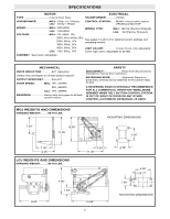
edge of door A REVERSING EDGE IS STRONGLY RECOMMENDED FOR ALL COMMERCIAL OPERATOR INSTALLATIONS. REQUIRED WHEN THE 3 BUTTON CONTROL STATION IS OUT OF SIGHT OF DOOR OR ANY OTHER CONTROL (AUTOMATIC OR MANUAL) IS USED. MGJ WEIGHTS AND DIMENSIONS HANGING WEIGHT:..........80-110 LBS. 7.50" 10.50 - LiftMaster LGJ | LGJ Manual - Page 3
for model LGJ. See Figure 1. 22.-715/4fo" r MGJ, butt together for LGJ FIGURE 1 OPERATOR PREPARATION Model LGJ: Shipped from the factory for right hand mounting, refer to preparation instructions on page 4 for Left hand mounting. Model MGJ: Shipped from the factory for either left hand or - LiftMaster LGJ | LGJ Manual - Page 4
chain to hang freely when the operator is mounted on right side only. To insure smooth operation of the disconnect chain assembly when 9 for for complete instructions on setting of limit switches. 2. Thread the release cable through the slot on the outermost edge of the support bracket, as shown in - LiftMaster LGJ | LGJ Manual - Page 5
SUPPORT BRACKET RELEASE CABLE SLOT HOUR GLASS CABLE SLEEVE KEY RING FIGURE 2 SASH CHAIN Disconnect Cable Re-routed for Left Hand Mounting LABEL SILK SCREEN FIGURE 3 5 - LiftMaster LGJ | LGJ Manual - Page 6
4. OPTIONAL (LGJ) Mounting Bracket OPTIONAL (MGJ) Mounting Bracket P/N 10-9098 Typical Right Hand Wall Mounted Operator FIGURE 3 IMPORTANT: The shelf or bracket must provide adequate support, prevent play between operator and door shaft, and permit operator to be fastened securely and with the - LiftMaster LGJ | LGJ Manual - Page 7
CAUTION TURN OFF POWER TO THE OPERATOR BEFORE MANUALLY OPERATING YOUR DOOR. Pull sash chaiWn anAd sRecNureING in bracket for manual operation of the door. This operator a floor level disconnect chain to disconnect the door from the door operator allowing for manual operation of the door in case of - LiftMaster LGJ | LGJ Manual - Page 8
operator. If not pre-installed by the door manufacturer, mount the sensing edge on the door according to the instructions operator as described below. b) Electrician must hardwire the junction box to the operator electrical box in accordance with local codes. MGJ MANUALLY If other problems persist, - LiftMaster LGJ | LGJ Manual - Page 9
nears the end of the shaft, it activates a switch(es). B. Manually raise the door to a nearly open position. (see page 17, Manual Operation) WARNING C. Depress the limit nut retaining bracket away from the slots in the limit nuts, and manually rotate to the OPEN limit nut until it depresses the OPEN - LiftMaster LGJ | LGJ Manual - Page 10
whenever a malfunction is observed or suspected. CAUTION: BEFORE SERVICING, ALWAYS DISCONNECT OPERATOR FROM POWER SUPPLY. HOW TO ORDER REPAIR PARTS OUR LARGE SERVICE ORGANIZATION SPANS AMERICA INSTALLATION AND SERVICE INFORMATION ARE AVAILABLE 6 DAYS A WEEK CALL OUR TOLL FREE NUMBER - 1-800-528 - LiftMaster LGJ | LGJ Manual - Page 11
wiring. MODEL MGJ Standard C2 or B2 Wiring Model MGJ operators are shipped manual will not apply. Refer only to the replacement wiring diagram for all connections. IMPORTANT NOTE: If your wiring diagram is missing, or you are unsure of the wiring type for your operator, contact the customer service - LiftMaster LGJ | LGJ Manual - Page 12
1754 SINGLE PHASE SCHEMATIC DIAGRAM for MGJ (OPTIONAL) LIGHT W MAX. 100W (OPTIONAL) BIMETAL RELAY C B BK A W WIRE NUT CLOSE-B BL Y C N.O. W RES. Y (HOT) L2 BK OPEN-A Y CAPACITOR R MOTOR * BK O/L L1 (N) BR R BK 3 STOP 4 Y MOVE - LiftMaster LGJ | LGJ Manual - Page 13
1819 THREE PHASE SCHEMATIC DIAGRAM for MGJ 230V BRAKE (WHEN PRESENT) 230V BRAKE (WHEN PRESENT) BRN GY PUR YEL BRN BL/BK 1 74 2 85 3 96 O/L* BL/BK BRN GY PUR YEL BRN - LiftMaster LGJ | LGJ Manual - Page 14
1666 SINGLE PHASE SCHEMATIC DIAGRAM for LGJ 14 - LiftMaster LGJ | LGJ Manual - Page 15
LGJ CONTROL CONNECTION DIAGRAM 41B6 LISTED DOOR OPERATOR NUMBERED BOXES CORRESPOND WITH TERMINALS ON J1 CONNECTOR STRIP If Neccessary, Remove The Connector Block From The Board To Secure Each Wire Connection Connect field - LiftMaster LGJ | LGJ Manual - Page 16
LGJ Below are replacement kits available for your operator. Optional modifications and/or accessories included with your operator may add or remove certain components from these lists. Please consult a parts and service representative regarding availability of individual components of kits specified - LiftMaster LGJ | LGJ Manual - Page 17
LGJ ELECTRICAL BOX - ILLUSTRATED PARTS L3 1 L1 L10 L5 L9 7 L10 L3 L8 L7 L2 WARNING 4 3 S2 WARNING S8 S1 S6 S3 S4 S5 2 6 5 S7 L2 L6 L10 L4 8 9 17 - LiftMaster LGJ | LGJ Manual - Page 18
optional modifications and/or accessories are included with your operator, certain components may be added or removed from these lists. Individual components of each kit may not be available. Please consult a parts and service representative regarding availability of individual components. Refer to - LiftMaster LGJ | LGJ Manual - Page 19
LGJ ILLUSTRATED PARTS D3 1 D11 D12 D5 D1 D9 3 D7 D2 D8 D6 D13 D4 D9 19 5 2 7 8 4 6 D10 - LiftMaster LGJ | LGJ Manual - Page 20
your operator may add or remove certain components from these lists. Please consult a parts and service representative #6-32 2 K72-12565 LIMIT SHAFT ASSEMBLY KIT Item P/N Description Qty L1 11-11373 MGJ Limit Shaft 1 L2 12-10458 3/8" Bearing, Plastic Flange 2 L3 13-10024 Limit Nut - LiftMaster LGJ | LGJ Manual - Page 21
MGJ ELECTRICAL BOX - ILLUSTRATED PARTS 1 L8 L6 L2 9 S3 S9 S7 S4 S6 S3 S5 6 S2 S8 6 8 S3 S7 5 S1 S6 S4 S3 10 L3 L1 L7 3 L3 7 4 L2 L5 L4 2 21 - LiftMaster LGJ | LGJ Manual - Page 22
optional modifications and/or accessories are included with your operator, certain components may be added or removed from these lists. Individual components of each kit may not be available. Please consult a parts and service representative regarding availability of individual components. Refer to - LiftMaster LGJ | LGJ Manual - Page 23
D8 D13 D4 D13 D2 D12 D5 D14 D11 2 4 ILLUSTRATED PARTS - MODEL MGJ 23 D3 3 1 D10 D9 D7 5 D1 D15 D6 D15 - LiftMaster LGJ | LGJ Manual - Page 24
MGJ CONTROL CONNECTION DIAGRAM IMPORTANT NOTES: (Refer to page 15 for model LGJ control connections) 1) The 3-Button Control Station provided must be connected for operation. ATTENTION ELECTRICIAN: 2) If a STOP button is not used, a jumper must be placed between termianls 3 and 4. USE 16 GAUGE
-
 1
1 -
 2
2 -
 3
3 -
 4
4 -
 5
5 -
 6
6 -
 7
7 -
8
-
9
-
10
-
11
-
12
-
13
-
14
-
15
-
16
-
17
-
18
-
19
-
20
-
21
-
22
-
23
-
24
 |
 |

OWNER'S MANUAL
MODELS:
LGJ & MGJ
INDUSTRIAL DUTY DOOR OPERATOR
NOT FOR RESIDENTIAL USE
LISTED
DOOR
OPERATOR
41B6
Serial #
(located on electrical box cover)
Installation Date
Wiring Type
2
YEAR
WARRANTY