LiftMaster LGJ LGJ Manual - Page 4
LGJ LEFT HAND MOUNTING PREP, Recon Disconnect Chain Assembly, Set Limit Switch Direction - inc
 |
View all LiftMaster LGJ manuals
Add to My Manuals
Save this manual to your list of manuals |
Page 4 highlights
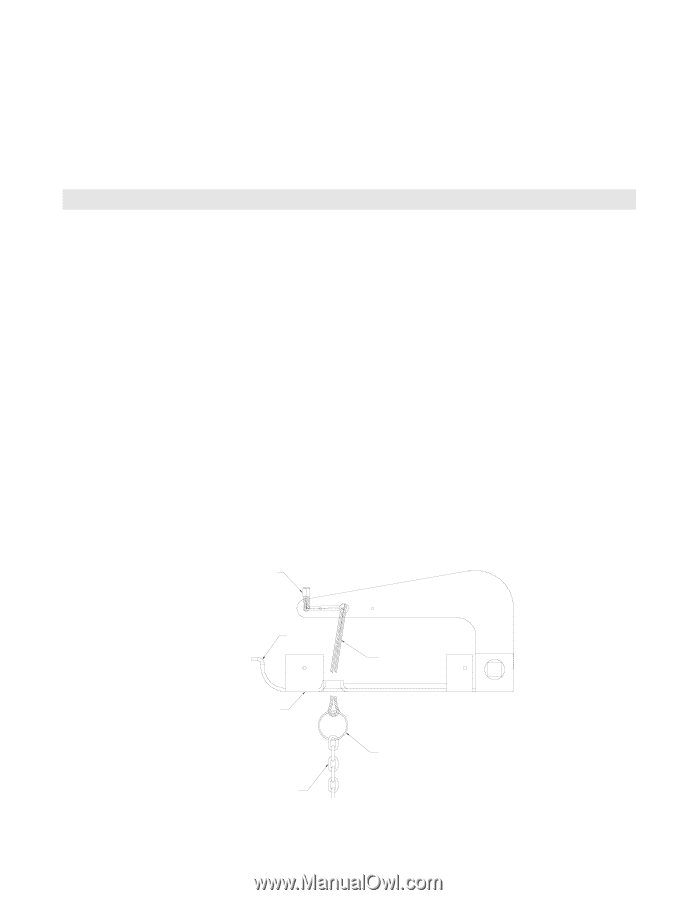
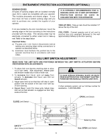
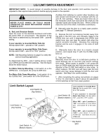
Remove the three cotter pins from the disconnect shaft. Do not discard the pins. Slide the disconnect shaft out of the support bracket. The release lever will now be free inside the motor frame. Remove the release lever and sash chain from the motor frame. Slide the disconnect hub, compression spring, and flatwasher from the end of the gear reducer shaft. Remove the disconnect support bracket by first removing the the two gear reducer housing screws. Replace the screws in the gear reducer and firmly tighten. 2. Re-assemble Disconnect Assembly Remove the two screws on the opposite side of the gear reducer and mount the disconnect support bracket with the notched side facing the motor. For the remainder of the installation, follow the steps outlined above in reverse order, referring to the illustration as necessary. LGJ LEFT HAND MOUNTING PREPARATIONS LGJ Operators are assembled at the factory to be installed in a right hand (motor side up) configuration. To install an LGJ Operator on the left hand side of your door (motor side down), complete the three steps described below. 1. Reconfigure Disconnect Chain Assembly The default configuration for the disconnect chain assembly is shown in Figure 1. This configuration allows the chain to hang freely when the operator is mounted on right side only. To insure smooth operation of the disconnect chain assembly when mounted motor side down, reconfigure as described below and as shown in figures 2 and 3. 1. Disconnect the key ring from the release cable. 2. Set Limit Switch Direction Locate Switch #1 on PCB in the electrical box. Place pole #2 of Switch #1 in the "OFF" position. With this setting limit switch labeled "A" is the close switch, limit switch labeled "B" is the open switch. IMPORTANT: Refer to page 9 for for complete instructions on setting of limit switches. 2. Thread the release cable through the slot on the outermost edge of the support bracket, as shown in Figure 2. 3. Re-attach the key ring and sash chain to the end of the loop of release cable. 3. Affix Electrical Box Cover Caution Label Place the caution label on electrical box cover such that the text is read in the opposite direction of silkscreen. HOUR GLASS CABLE SLEEVE FIGURE 1 SLOT RELEASE CABLE SUPPORT BRACKET KEY RING SASH CHAIN Disconnect Cable as shipped from the factory 4
-
 1
1 -
 2
2 -
 3
3 -
 4
4 -
 5
5 -
 6
6 -
 7
7 -
 8
8 -
 9
9 -
 10
10 -
11
-
12
-
13
-
14
-
15
-
16
-
17
-
18
-
19
-
20
-
21
-
22
-
23
-
24
 |
 |