LiftMaster MAS Quick Start Guide - Page 2
Features And Functions, Control Board Layout - reset
 |
View all LiftMaster MAS manuals
Add to My Manuals
Save this manual to your list of manuals |
Page 2 highlights
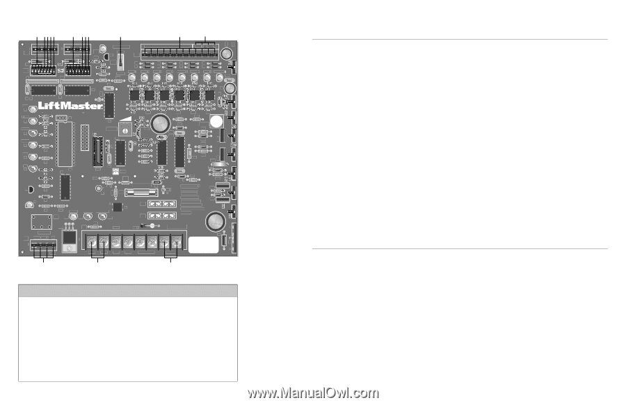
CONTROL BOARD LAYOUT A BCDE F GH I J K L 1 1 J2 AUX LIMITS M/S D8 S1 12 R1 R12 J3 R14 R16 MANUAL 1 2 3 4 5 6 7 8 9 1Ø 11 12 OPEN Q2 J5 S3 T2 T1 OPEN 1 OPEN 2 CLOSE R21 T4 T3 OPEN 3 AUX 4 T6 T8 T5 T7 SAFETY 5 CLOSE 6 BACK 7 SHADOW C16 C3 U4 C19 D15 D16 D17 D18 D19 D22 D23 D24 C1 U1 C2 OLS D7 OPEN D6 BRAKE D5 CLOSE D4 CLS D3 IRD D2 Q1 J1 1 X1 U6 IRD1 U7 X2 R7 R6 U3 U2 C4 CPU R19 JP2 F2 R3 + R2Ø C5 F1 R15 D1 D9 + B1 R2 R11 HBEAT BAT LO AC POWER K1 D11 D12 D14 R13 U19 J4 BAT- Aux Relay C NC NO DC 1 R33 R39 R44 R48 R59 R43 R43 D21 R63 R25 R58 C12 U12 DX3 DX4 D27 1A DC C8 F4 F3 MOV D29 R57 C13 R56 DX2 R51 D2Ø R55 WARNING FOR R62 C2Ø CONTINUOUS + PROTECTION AGAINST FIRE DX1 REPLACE ONLY WITH THE SAME TYPE AND RATING OF FUSE MOTOR TR PWR ACC+ ACC- BAT- BAT+ 24VAC XFMR MOTOR - B2 + M N PROGRAMMING INPUTS S1-DIP SWITCHES A DIP Switches S1-1 to S1-4 FAST RUN TIMER B DIP Switch S1-5 SINGLE BUTTON FUNCTION C DIP Switch S1-6 CLUTCH OPTION D DIP Switch S1-7 HANDING THE BARRIER ARM E DIP Switch S1-8 K1 RELAY (OPTIONAL) S2-DIP SWITCHES F DIP Switches S2-1 to S2-5 TIMER-TO-CLOSE G DIP Switch S2-6 MULTIPLE VEHICLE MEMORY H DIP Switch S2-7 AUTO CLOSE I DIP Switch S2-8 FAIL SAFE O INPUT/OUTPUT LOCATIONS J S3 Manual Switch K J5 Wiring Inputs L J5 Common (COM) Wiring Inputs M K1 Relay (optional) and Terminal Strip (J1) N Accessory Output Power (300 mA) max. O Motor Wiring Connections 01-35926 C18 C15 F5 C2 FEATURES AND FUNCTIONS S1 DIP SWITCHES A FAST RUN TIMER (FULL SPEED RUN TIMER) DIP Switch S1-1 to S1-4 When the gate operator activates, it ramps up and slows down for a fixed amount of time, but will run at full speed for variable amounts of time depending upon the settings of the S1-1 to S1-4 DIP switches. Each DIP switch represents increments of 1/8 second. When DIP switches S1-1, S1-2 and S1-3 are in the ON position, the Fast Run Timer is set to 2-3/8 seconds by factory default. When DIP switches S1-1 to S1-4 are set in the OFF position, the full speed run time is 1-1/2 seconds. The longer the operator runs at full speed, the less ramp up and slow down time. When adjusting, make sure the Fast Run Timer settings DO NOT overrun the slow down time. B SINGLE BUTTON FUNCTION DIP Switch S1-5 With S1-5 DIP switch in the ON position, the Single Button Function (Command to Open/Command to Close) will activate, with inputs on terminal 4 and Common (COM) on the J5 terminal strip. Any of the terminals 9-12 on the J5 terminal strip can be used for common. When using this feature with the radio receiver (provided), move the radio wire from terminal 1 to terminal 4 on the J5 terminal strip. C CLUTCH OPTION DIP Switch S1-6 With S1-6 DIP switch in the ON position, and using the Clutch Option; when the barrier arm is manually forced UP (OPEN), the barrier arm will automatically CLOSE. If the Close Loop detects tailgating, the K1 Relay will activate. If an anti-tailgating alarm is wired into terminal strip (J1), an alarm will sound. NOTE: When using the Clutch Option, turn DIP switches S1-6 and S2-7 to the ON position (Auto Close). When this feature is activated the barrier arm will CLOSE by the timer whenever it is forced UP (OPEN). D HANDING THE BARRIER ARM DIP Switch S1-7 The J4 Motor Wiring is controlled by DIP switch S1-7. The Handing of the Barrier Arm may be changed from right-hand to left-hand operation by reversing the factory default motor connections. NOTE: Right-hand or left-hand operation is determined by facing the control board with the barrier arm in the CLOSED position. If the barrier arm is to the right, it is set for right-hand gate operation. 1. For left-hand operation reverse the motor wires on J4-7 (blue wire) and J4-8 (orange wire) (see illustration example "D" on reverse side). 2. Set DIP switch S1-7 to the ON position. 3. Turn the Limit Cam (see backside of control board) until the barrier arm is in the CLOSED position. 4. Turn the Limit Cam position 90 degrees to the left until the magnet is just behind the limit sensor (see illustration example "F" on reverse side). The barrier arm will now be in the OPEN position. 5. Cycle the power and test the Handing of the Barrier Arm. E K1 RELAY (OPTIONAL) DIP Switch S1-8 Auxiliary devices such as Counters, Alarms, Buzzers, and SAMS (Sequence Access Management System), can be wired into the K1 Relay and terminal strip (J1). When S1-8 DIP switch is in the OFF position, the K1 Relay will activate throughout the OPEN cycle. When S1-8 DIP switch is in the ON position, the K1 Relay will be activated briefly until the OPEN LIMIT (OLS) is reached. S2 DIP SWITCHES F TIMER-TO-CLOSE DIP Switch S2-1 to S2-5 The S2-1 to S2-5 DIP switches will set the period of time the gate remains opened after reaching the OPEN position. Each DIP switch represents the number of seconds the gate will remain OPEN before CLOSING. With the S2-3 DIP switch in the ON (factory default) position, there are 4 seconds to allow a vehicle enough time to move out of the path of the closing barrier arm. Turning multiple switches ON will combine the amount of time the barrier arm remains OPEN. The maximum hold OPEN time is 32 seconds. To de-activate this feature turn S2-7 DIP switch to the OFF position. G MULTIPLE VEHICLE MEMORY DIP Switch S2-6 With S2-6 DIP switch in the ON position, the Multiple Vehicle Memory will activate, with inputs on terminal 4 and Common (COM) on the J5 terminal strip. Any of the terminals 9-12 on the J5 terminal strip can be used for common. NOTE: With Multiple Vehicle Memory activated, the barrier arm will remain OPEN until the pre-authorized number of vehicles pass over the Close Loop. ©2010 The Chamberlain Group, Inc. All Rights Reserved H AUTO CLOSE DIP Switch S2-7 The S2-7 DIP switch (Auto Close) should be activated in case one or more of the pre-authorized vehicles DO NOT pass through the gate. The barrier arm will close after the set amount of time elapses and the count memory is reset to zero. I FAIL SAFE (AUTO OPEN ON AC POWER FAILURE) DIP Switch S2-8 With S2-8 DIP switch in the ON position, the barrier arm will automatically OPEN approximately 15 seconds after a loss of power. Once the power has been restored the operator will resume normal operation after any input. With S2-8 DIP switch in the OFF position, the barrier arm will resume normal operation until the batteries drop below 50% at which time the barrier arm will OPEN and remain opened until the batteries are fully charged.
-
 1
1 -
 2
2
 |
 |