LiftMaster MAS Owners Manual - Page 15
Adjustments, Warning
 |
View all LiftMaster MAS manuals
Add to My Manuals
Save this manual to your list of manuals |
Page 15 highlights
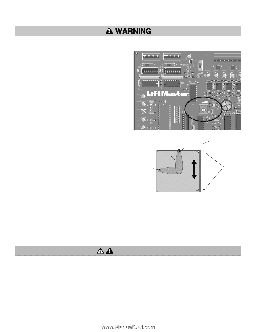
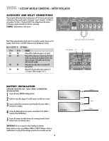
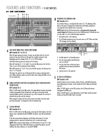
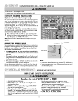
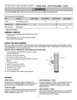
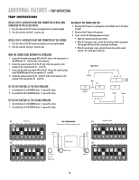
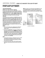
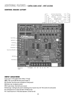
ADJUSTMENTS » INSTANT REVERSE DEVICE (IRD) + INSTALL THE BARRIER ARM To reduce the risk of SERIOUS INJURY or DEATH: • Disconnect power BEFORE performing ANY adjustments near drive shaft. INSTANT REVERSE DEVICE (IRD) Adjustments to be done by qualified service persons only. The instant reverse device is an internal circuit that continuously monitors the motor's current for increased draw in order to detect obstructions. If the arm is obstructed while closing the arm will reverse to the open position, time out (using the time delay set at S-2 switches 1-5) and then close. If arm is obstructed while opening, the arm will stop, time out (using the time delay set at S-2 switches 1-5) and then close. Turning the IRD1 right (clockwise more sensitive), or left (counter clockwise less sensitive) in small increments will allow sensitivity adjustments (IF ARM DOES NOT REVERSE, DO NOT CONTINUE TO FORCE). 1 Place an obstruction in the path of the arm. Adjust sensitivity so that consistent reversal occurs when the arm hits the obstruction. If the gate stops while opening then the IRD is TOO sensitive. NOTE: Instant reverse device (IRD) should be tested monthly to ensure proper operation. C1 X2 D16 D17 D18 D19 1 1 J2 AUX LIMITS M/S U1 OLS D7 OPEN X1 D6 BRAKE D5 CLOSE D4 CLS D3 MANUAL 1234567 J3 R14 OPEN Q2 J5 S3 T2 T4 T6 T1 T3 T5 OPEN 1 OPEN 2 OPEN 3 AUX 4 SAFET C3 R24 R35 R41 R46 U6 IRD1 U7 ADJUST THE BARRIER ARM Location of limit sensor (Operator Chassis) The arm should be level in the HORIZONTAL POSITION. If the arm is not level it can be adjusted by sliding the control board and/or adjusting the limit cam. The control Limit Cam board has two sensors on the back of the control board that sense when the limit cam has reached the open and close limit. • If the arm is closing too far: Loosen the control board screws and slide the Location of limit sensor Control Board Screws WARNING control board UP to increase the time it takes for the limit cam to travel between each sensor. • If the arm is not closing far enough: Loosen the control board screws and (Control Board) slide the control board DOWN to decrease the time it takes for the limit cam to travel between each sensor. • If the arm is not stopping at the limits: Move the limit cam closer to the NOTES: control board by loosening the set screw on the limit cam. • In some cases, additional adjustments may be required after the belt wears in. WARNING After any adjustment open and close the arm to test if the arm is level. Ensure the • To prevent entrapment, allow for two (2) feet minimum clearance past end of limit cam set screw and control board screws are tight when adjustments are done. arm when in down position. OPERATION AND MAINTENANCE » IMPORTANT SAFETY INSTRUCTIONS IMPORTANT SAFETY INSTRUCTIONS WARNING To reduce the risk of SEVERE INJURY or DEATH: 1. READ AND FOLLOW ALL INSTRUCTIONS. 5. Use the emergency release ONLY when the gate is not moving. 2. NEVER let children operate or play with gate controls. Keep the remote control away from children. 6. KEEP GATES PROPERLY MAINTAINED. Read the owner's manual. Have a qualified service person make repairs to gate hardware. 3. ALWAYS keep people and objects away from the gate. NO ONE SHOULD CROSS THE PATH OF THE MOVING GATE. 4. Test the gate operator monthly. The gate MUST reverse on contact with a rigid object or stop when an object activates the non-contact sensors. After adjusting the force or the limit of travel, retest the gate operator. Failure to adjust and retest the gate operator properly can increase the risk of INJURY or DEATH. 7. The entrance is for vehicles ONLY. Pedestrians MUST use separate entrance. 8. Disconnect ALL power BEFORE performing ANY maintenance. 9. ALL maintenance MUST be performed by a LiftMaster professional. 10. SAVE THESE INSTRUCTIONS. 15
-
 1
1 -
2
-
3
-
4
-
5
-
6
-
7
-
8
-
9
-
 10
10 -
 11
11 -
 12
12 -
 13
13 -
 14
14 -
 15
15 -
 16
16 -
 17
17 -
 18
18 -
 19
19 -
 20
20 -
21
-
22
-
23
-
24
 |
 |