LiftMaster MAST Quick Start Guide - Page 1
LiftMaster MAST Manual
 |
View all LiftMaster MAST manuals
Add to My Manuals
Save this manual to your list of manuals |
Page 1 highlights
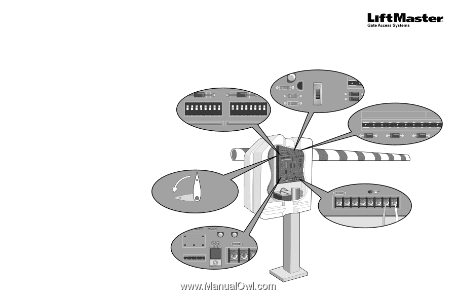
QuickStart programming guide for MEGA Arm Gate Operators MODELS MADCBB, MATDCBB, MASDCBB, & MASTDCB This Quick Start is intended to highlight the features and functions of the Mega Arm Gate Operator. Refer to the installation manual for complete information regarding installation and programming. INTRODUCTION The operator functions can be customized by changing various DIP switches, and wiring auxiliary devices to the control board on the J5 terminal strip. DEFAULT SETTINGS ARE AS FOLLOWS: • Timer-to-Close is activated and set to four seconds. • Radio receiver is wired to open only. • The barrier arm is set to right-hand gate operation. NOTE: Right-hand or left-hand operation is determined by facing the control board with the barrier arm in the CLOSED position. If the barrier arm is to the right, it is set for right-hand gate operation. • Motor speed is set to approximately 2.5 seconds of fast run time. • Fail Safe is set for Auto Open after batteries drop below 50%. OVERVIEW A The S1 and S2 DIP switches work together with devices wired into the J5 terminal strip. The DIP switch settings can be set to control various features such as K1 Relay (optional), Timer-to-Close, Single Button Function, and Fail Safe (Auto Open on AC Power Failure). B The S3 DIP switch is a service switch used to open and close the barrier arm from the control board. NOTE: The S3 DIP switch should be set to CLOSE for normal operation. C The J5 terminal strip is used for controlling the barrier arm with various accessories such as Receivers, Loop Detectors, Access Controls, and Push Button Stations. D The J4 Motor Wiring is controlled by DIP switch S1-7. The gate operator default setting for DIP switch S1-7 is in the OFF position, and set for right-hand gate operation. E The K1 Relay (optional) and terminal strip (J1) are used for auxiliary devices such as Counters, Alarms, Buzzers, and SAMS (Sequence Access Management System). A DIP Switches ON ON S1 S2 1 2345678 1 2345678 OFF OFF B Manual Switch MANUAL OPEN S3 CLOSE J5 C J5 Terminal Strip (Wiring Inputs) 123456789 J5 F Limit Cam Position CAM POSITION E K1 Relay (optional) and Terminal Strip (J1) K1 D J4 Motor Wiring (Factory default right-hand gate operation shown below.) MOTOR J4 ACC+ ACC- BAT- BAT+ 24VAC XFMR MOTOR Blue wire Orange wire AUX RELAY J1 C NC NO DC PWR
-
 1
1 -
 2
2
 |
 |