LiftMaster MAST Owners Manual - Page 12
Install The Receiver
 |
View all LiftMaster MAST manuals
Add to My Manuals
Save this manual to your list of manuals |
Page 12 highlights
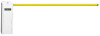
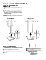
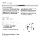
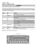
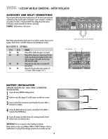
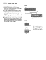
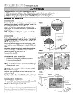
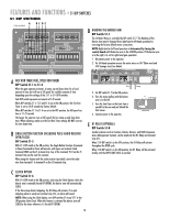
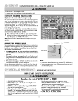
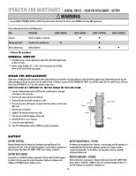
INSTALL THE RECEIVER » INSTALL THE RECEIVER To prevent possible SERIOUS INJURY or DEATH from a moving gate or garage door: • ALWAYS keep remote controls out of reach of children. NEVER permit children to operate, or play with remote control transmitters. • Activate gate or door ONLY when it can be seen clearly, is properly adjusted, and there are no obstructions to door travel. • ALWAYS keep gate or garage door in sight until completely closed. NEVER permit anyone to cross path of moving gate or door. INSTALL THE RECEIVER WIRING THE RECEIVER Contacts 1 and 2 on the receiver terminal strip are for power. The power terminals are unpolarized. Connect terminals 1 and 2 to the accessory power terminals on the J4 terminal strip at the bottom of the control board (Figure 1). Contacts 3 and 4 on the receiver terminal strip are for a common and a relay. Connect terminals 3 and 4 to terminals 1 and 10 on the J5 terminal strip at the top of the control board. NOTE: Auxiliary Pin 4 can be used for push to open/push to close functionality. SET SECURITY MODE The Universal Receiver can be used with up to 15 rolling code remotes or passwords in HIGH security mode. Alternately, it can be used with up to 31 of any type remote in NORMAL security mode, including any combination of rolling code, billion code (390 MHz only), or dip switch remotes. The jumper must be set at the HIGH position for the receiver to operate in HIGH security mode. It must be set at NORMAL position to operate at the NORMAL mode (Figure 2). When changing from NORMAL to HIGH security mode, any previous remote codes must be erased. Repeat Steps 2 and 3 in the Programming Section below to reprogram the receiver for each remote control in use. The receiver is factory set at HIGH. JJ55 FIGURE 1 C18 U18 C15 1 MANUAL 1 2 3 4 5 6 7 8 9 1Ø 11 12 UX LIMITS M/S J3 R14 Q2 OPEN J5 23 D1 456 R1Ø R9 R8 R7 R6 R5 R4 R3 D9 R2 C18 U18 C15 DJ121Ø 1 AUX LIMITS M/S J3 R14 S3 MANUAL R18 Q2 OPEN 1 2 3 4 5 6 7 8 9 1Ø 11 12 J5 T2 T1 T4 T3 T6 T5 T8 T7 78 D8 D1Ø S2S1 1 2345678 S2 1 2345678 R1 1 2R12 3 4 5 R18 S3 R17 T2 T4 T6 T8 R17 T1 T3 T5 T7 OPEN 1 OPEN 2 OPEN 3 AUX 4 SAFETY 5CLOSE 6 BACK 7SHADOW 8 CLOSE D24 D16 D15 6 R176 8R21 C3 R24 R35 R41 R46 R5Ø CLOSE C16 R61 OPEN 1 OPEN 2 OPEN 3 D17 R36 D18 R42 D19 R47 D22 R53 D23 R12 C2 U4 C19 U8 R3Ø R16 R21 U9 U11 U13 U14 U15 C2 F5 C1 U1 AUX 4 SAFETY 5CLOSE 6 BACK 7SHADOW 8 C16 D24 D17 R36 D18 R42 D19 R47 D22 R53 D23 D16 D15 R23 R34 R4Ø R45 R49 R6Ø OLS D7 OPEN X1 D6 R1Ø R9 BRAKE D5 R8 U6 R22 R33 R26 R39 R44 R43 C3 R48 R59 R43 D21 R63 U4 IRD1 R25 U5 C12 U12 R58 C22 R24 U16 U8 R3Ø R35 R41 R46 R5Ø R61 U9 U11 U13 U14 U15 C7 C19 F5 X2 C2 D27 CLOSE D4 U7 DX3 C6 U1Ø DX4 C2 R7 CLS R57 D29 D3 C13 R6 R56 Q6 Q5 Q4 D28 IRD D2 Q1 J1 1 U3 R5 U2 R4 R3 D9 C4 CPU R19 R2Ø + C5 JP2 F2 F1 R15 D1 + R2 R11 B1 HBEAT BAT LO AC POWER K1 D11 X1 U19 Aux Relay D12 R13 J4 D14 BAT- C NC NO DC 1 R38 R37 1A DC C8 C2Ø + F4 F3 DX2 R51 R55 D2Ø WARNING FOR R62 CONTINUOUS PROTECTION AGAINST FIRE DX1 REPLACE ONLY WITH THE SAME TYPE AND RATING OF FUSE MOV U6 MOTOR TR PWR ACC+ ACC- BAT- BAT+ 24VAC XFMR IRD1 MOTOR U5 D26 B2 + - D25 R23 R34 R22 R33 R26 R25 R4Ø R45 R49 R6Ø R39 R44 R48 R59 R43 R43 D21 R63 R58 P1 C12 U12 to J4 Accessory Power C22 U16 D27 U7 HBEAT BAT LO AC POWER C6 DX3 U1Ø P2 to J4 AccessoDryX4Power X2 C7 D11 D12 D14 U19 U3 U2 R13 J4 BAT- C4 1CPU R19 JP2 F2 MOV R38 R37 D29 P3 to J5 TerminaRl517 C13 P4 to J5 Terminal 10 R56 DX2 R51 R55 D2Ø D26 1A DC ACC+ ACC- BAT- BAT+ R2Ø C8 + R15 C5 F1 JJ44 C2Ø + WARNING FOR R62 CONTINUOUS PROTECTION AGAINST FIRE DX1 + F4 REPLACE ONLY WITH THE SAME R11 B1 HBEAT BAT LO AC POWER K1 D11 U19 D12 R13 J4 D14 - + BAT- F3 MOV 1 10 TYPE AND RATING OF1FUSE 2 3 MOT4OR D25 - FIGURE 2 Aux Relay C NC NO DC 1 P1-P4 TR Q6 Q5 Q4 D28 B2 Security Mode Terminals Jumper Security Mode Terminals Jumper PROGRAMMING THE REMOTE TO THE RECEIVER 1 Pry open the front panel of receiver case with a coin or a screwdriver. Re-connect power to opener (Figure 3). 2 Press and release the "learn" button on the receiver. The learn indicator light will glow steadily for 30 seconds. 3 Within 30 seconds, press and hold the button on the hand-held remote that you wish to operate your gate. The operator will now operate when the push button on either the receiver or the remote control is pressed. Repeat Steps 2 and 3 for each remote control that will be used to operate the gate. TO ERASE ALL REMOTE CONTROL CODES 1 Press and hold the "learn" button on the receiver panel until the indicator light turns off (about 6 seconds). All remote codes are now erased. Follow the steps above to reprogram each remote control. HIGH SECURITY MODE FIGURE 3 OPENING RECEIVER OPEN RECEIVER Connect Antenna 24V 12V NOTICE: To comply with FCC and or Industry Canada (IC) rules, adjustment or modifications of this receiver and/or transmitter are prohibited, except for changing the code setting or replacing the battery. THERE ARE NO OTHER USER SERVICEABLE PARTS. Tested to Comply with FCC Standards FOR HOME OR OFFICE USE. Operation is subject to the following two conditions: (1) this device may not cause harmful interference, and (2) this device must accept any interference received, including interference that may cause undesired operation. 12 HIGH NORM Indicator Light Learn Button C P2 M (Not Provided) NORMAL SECURITY MODE Output Duration Terminals Security Mode Power Supply Jumper
-
 1
1 -
2
-
3
-
4
-
5
-
6
-
 7
7 -
 8
8 -
 9
9 -
 10
10 -
 11
11 -
 12
12 -
 13
13 -
 14
14 -
 15
15 -
 16
16 -
 17
17 -
18
-
19
-
20
-
21
-
22
-
23
-
24
 |
 |