LiftMaster MHS MJ5011E Installation-2008 Manual - Page 15
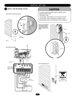
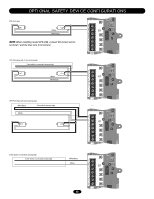
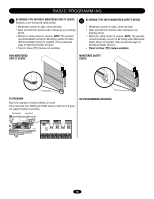
When installing model CPS-LN4, connect the brown wire to, terminal 1 and the blue wire to terminal 2.
 |
View all LiftMaster MHS manuals
Add to My Manuals
Save this manual to your list of manuals |
Page 15 highlights
ANT X ANT TTC ^^^^ 1 LEARN STOP CLOSE OPEN LEDD14 2 3 45 LMEP1 LMEP2 COM INTRLK STOP CLOSE OPEN 67 OPTIONAL SAFETY DEVICE CONFIGURATIONS CPS Photo-Eyes (White) (White/Black) NOTE: When installing model CPS-LN4, connect the brown wire to terminal 1 and the blue wire to terminal 2. CPS Photo-Eyes with 2-wire sensing edge 2-wire electric or pneumatic sensing edge (White) (White/Black) AUX ANT AUX ANT TTC ^^^^ 1 LEARN STOP CLOSE OPEN LEDD14 2 3 4 LMEP1 LMEP2 COM INTRLK STOP CLOSE OPEN 5 6 7 AUX ANT AUX ANT CPS Photo-Eyes with 4-wire sensing edge (White/Black) 4-wire electric sensing edge (White) TTC ^^^^ 1 LEARN STOP CLOSE OPEN LEDD14 2 3 4 LMEP1 LMEP2 COM INTRLK STOP CLOSE OPEN 5 6 7 AUX ANT AUX ANT TTC ^^^^ 1 LEARN STOP CLOSE OPEN LEDD14 2 3 4 LMEP1 LMEP2 COM INTRLK STOP CLOSE OPEN 2-Wire electric or pneumatic sensing edge 2-wire electric or pneumatic sensing edge (White/Black) (White) 15 5 6 7
-
 1
1 -
2
-
3
-
4
-
5
-
6
-
7
-
8
-
9
-
 10
10 -
 11
11 -
 12
12 -
 13
13 -
 14
14 -
 15
15 -
 16
16 -
 17
17 -
 18
18 -
 19
19 -
 20
20 -
21
-
22
-
23
-
24
-
25
-
26
-
27
-
28
-
29
-
30
-
31
-
32
 |
 |
