LiftMaster RSL12U RSL12U Site Plan Manual - Page 2
Outside, Property - model
 |
View all LiftMaster RSL12U manuals
Add to My Manuals
Save this manual to your list of manuals |
Page 2 highlights
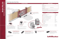
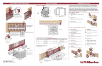
GATE CONSTRUCTION & SITE PREPARATION Closing Gate Safety Catch Rollers Install catch rollers with safety covers on the side of a post or wall with a minimal distance of half an inch (1.27 cm) between the rollers and gate. Warning Placard on both sides of gate. Closing Gate DO NOT use a gate catch post. 2-1/4 inch (5.7 cm) wire grid safety screen 48 inches (121.9 cm) high. Maximum gate weight: 800 lbs (363.6 kg) Low Voltage UL approved conduit High Voltage UL approved conduit Earth Ground Rod Weld physical stops on ends of gate rail. 24" (61 cm) Concrete Pad 6" (15.2 cm) Above Ground Below the frost line. Check all national and local codes. Minimum of 24" (61 cm) recommended in regions with no frost line. 24" (61 cm) INSTALLATION OVERVIEW OPERATOR DIMENSIONS MOUNTING FOOTPRINT 20-3/8" (51.8 cm) 7.49" (19 cm) 15-3/16" (38.6 cm) 10-1/2" (26.7 cm) 13.65" (34.7 cm) 1/2" (1.8 cm) (Gate) 1" - 2" (2.5 - 5.1 cm) CONDUIT LOCATION 24" (61 cm) 24" (61 cm) STANDARD DUAL GATE INSTALLATION Wire Gauge 18 16 14 12 10 OPERATOR POWER SOURCE EXTERNAL PLUG-IN TRANSFORMER (24 VAC) Wire Gauge DIRECT PLUG-IN TRANSFORMER (120 VAC) 150 feet (46 m) 14 1150 feet (351 m) 250 feet (76 m) 12 1850 feet (564 m) 400 feet (122 m) 10 2950 feet (899 m) 600 feet (183 m) 1,000 feet (305 m) NOTE: Use copper conductors ONLY. NOTE: Wired connection in a dual gate setup is optional. Operators can be setup for wireless dual gate communication. Warning Sign Edge Sensor OPurtosipdeerty Safety Catch Roller Edge Sensor Operator Photoelectric Sensors Earth Ground Rod Check national and local codes for proper depth InPsroidpeerty Water Tight Conduit (Not provided) NOTE: Power and control wiring MUST be run in separate conduits. ENTRAPMENT PROTECTION This operator contains an inherent (internal) entrapment protection system and REQUIRES the addition of a LiftMaster external monitored entrapment protection system (non-contact photoelectric sensor or contact edge sensor) for EACH entrapment zone prior to gate movement. An entrapment zone is every location or point of contact where a person can become entrapped between a moving gate and a stationary object. Your application may contain one or many entrapment zones. System includes three monitored entrapment protection inputs capable of covering all entrapment zones (and a total of six inputs with the optional expansion board). Use only LiftMaster approved entrapment protection devices. NON-CONTACT SENSORS Model LMTBU LiftMaster Monitored Through Beam Photoelectric Sensor Model LMRRU LiftMaster Monitored Retro-Reflective Photoelectric Sensor NOTE: LMRRU is provided with the operator ProIpnesridtye PrOopuetsrtidye Model CPS-UN4 LiftMaster Commercial Protector System® PrOopuetsritdye ProIpnesridtye CONTACT SENSORS (EDGE SENSORS) Model LMWEKITU LiftMaster Monitored Wireless Edge Kit (Transmitter and Receiver) Model LMWETXU LiftMaster Monitored Wireless Edge Transmitter Model L50 Large Profile Monitored Edge (82 ft. roll) Model L50E Large Profile Ends Kit (pair, pack of 10) Model L50CHP Channel for both Large and Small Profiles PVC (8 ft., pack of 10) Model L50CHAL Channel for both Large and Small Profiles Aluminum (10 ft., pack of 8) Model S50 Small Profile Monitored Edge (82 ft. roll) Model S50E Small Profile Ends Kit (pair, pack of 10) Models L504AL, L505AL, and L506AL Large Profile Edge - Aluminum Channel (4 ft, 5 ft, 6 ft) Models S504AL, S505AL, and S506AL Small Profile Edge - Aluminum Channel (4 ft, 5 ft, 6 ft) Model ETOOL Edge Cutting Tool Models WS4, WS5, and WS6 Wraparound Square Monitored Edge (4 ft, 5 ft, 6 ft) Models WR4, WR5, and WR6 Wraparound Round Monitored Edge (4 ft, 5 ft, 6 ft) PrOouptesritdye ProIpnesridtye ProIpnesridtye PrOouptesritdye
-
 1
1 -
 2
2
 |
 |