LiftMaster RSW12V RSL12V Wiring Diagram Manual - Page 2

Swing, &warning

Page 2 highlights

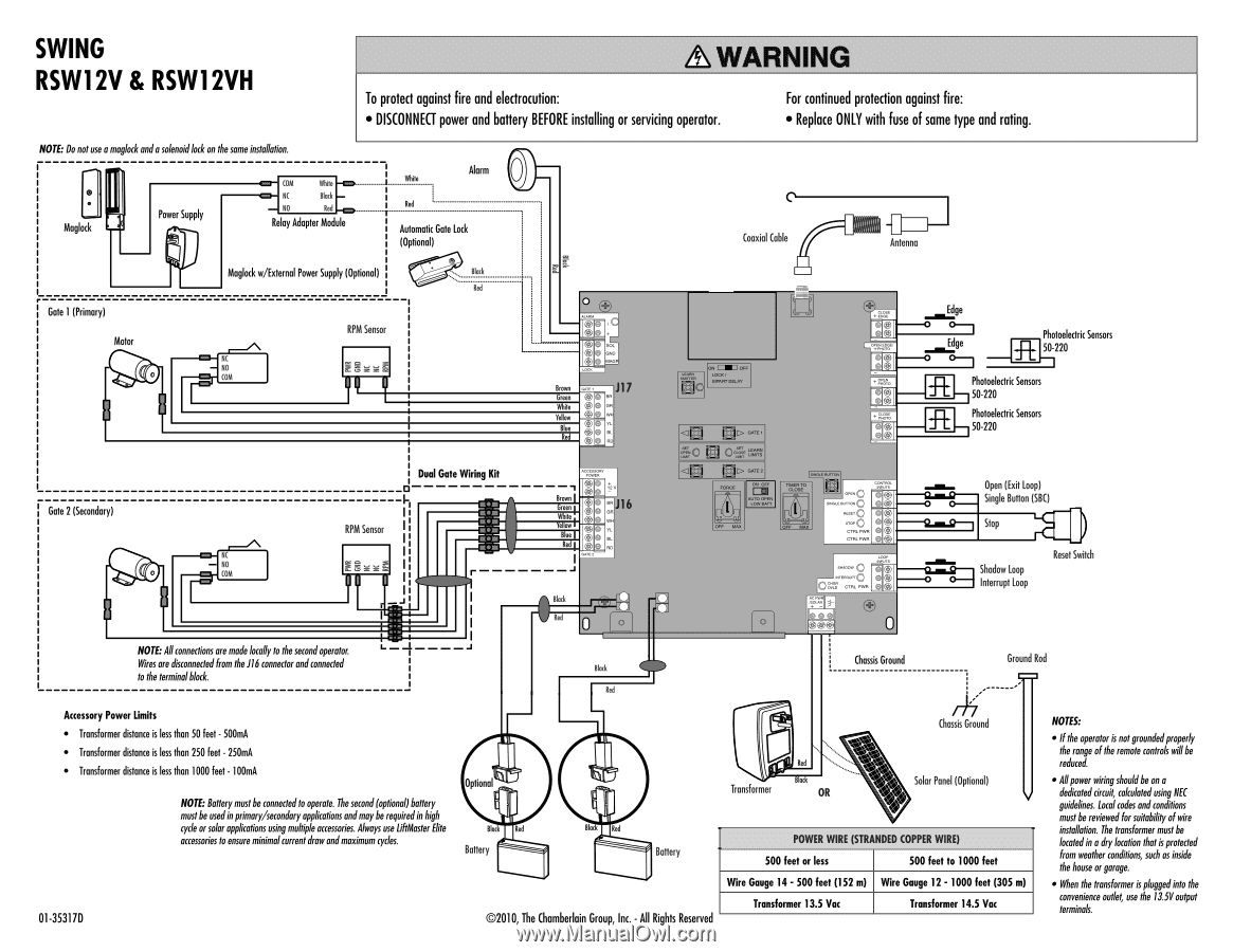
SWING RSW12V & RSW12VH &WARNING To protect against fire and electrocution: • DISCONNECT power and battery BEFORE installing or servicing operator. For continued protection against fire: • Replace ONLY with fuse of same type and rating. NOTE: Do notuse amaglodc anda solenoidlock on the same installation. • Magi ck Power Supply COM White NC Block NO Red R lay Adapter Mod le Marra Re --r-- bit Automatic Gate Lock (Optional) Coaxial Cable Antenna 0 Maglock w/External Power Supply (Optional) Block L Red Gate 1 (Primary) RPM Sensor Motor NC NO COM Gate 2 (Secondary) NC NO 0 COM Dual Gate Wiring Kit RPM Sensor NOTE:Al connections are madelocally to the secondoperator. Wires are disconnected from the116 connector andconnected to the terminalblock. Brown R J17 Green • we. • OR Yellow • lug • • • Brown rein mite :00 000 J16 ow B us 0 aa Block Red Black aN CMD OFF Lg,/ tea 0 RIPART DELAY

  • 1
  • 2

SWING
RSW1
2V
&
RSW1
2VH
NOTE:
Do
not
use
a
maglodc
and
a
solenoid
lock
on
the
same
installation.
&WARNING
To
protect
against
fire
and
electrocution:
For
continued
protection
against
fire:
DISCONNECT
power
and
battery
BEFORE
installing
or
servicing
operator.
Replace
ONLY
with
fuse
of
same
type
and
rating.
Power
Supply
Magi
ck
COM
White
NC
Block
NO
Red
Re
bit
Marra
R
lay
Adapter
Mod
le
--
r
--
Automatic
Gate
Lock
(Optional)
Maglock
w/External
Power
Supply
(Optional)
L
__________
----------------------------------
Gate
1
(Primary)
Motor
NC
NO
COM
RPM
Sensor
0
Block
Red
Coaxial
Cable
Antenna
Brown
Green
we.
Yellow
lug
Gate
2
(Secondary)
0
NC
NO
COM
RPM
Sensor
Dual
Gate
Wiring
Kit
NOTE:
Al
connections
are
made
locally
to
the
second
operator.
Wires
are
disconnected
from
the
116
connector
and
connected
to
the
terminal
block.
Accessory
Power
limits
Transformer
distance
is
less
than
50
feet
-
500mA
Transformer
distance
is
less
than
250
feet
-
250mA
Transformer
distance
is
less
than
1000
feet
-
100mA
NOTE:
Battery
must
be
connected
to
operate.
The
second
(optional)
battery
must
be
used
in
primary/secondary
applications
and
may
be
required
in
high
cy
de
or
solar
applications
using
multiple
accessories.
Always
use
LiftMaster
Elite
accessories
to
ensure
minimal
current
draw
and
maximum
cycles.
Brown
rein
mite
ow
B
us
R
J17
OR
Optional
Battery
Block
:0
0
00
0
0
aa
Red
J16
te
a
0
a
N
CMD
OFF
Lg,/
RIPART
DELAY
<1
CY—
o
oo
L
tk
r
,
,In
<IEI
D>
FORCE
Olc±i
3
:1FF
ALTO
OPEN
LOW
BATT
L
2,O
0
Edge
Edge
O
fE
Photoelectric
Sensors
50-220
Photoelectric
Sensors
50-220
Photoelectric
Sensors
=a®
-IR
I--
1
50-220
',INERT]
0
•—•—
^0
,
0
O
Open
(Exit
Loop)
g-
-
Ci•m
Single
Button
(SBC)
_
o
c
o
_
67.m.i2—i
Stop
‘4`-ci.
m
g
Shadow
Loop
0
.TRL
F.R
Interrupt
Loop
0(061)
0
Black
Ole
Battery
01-35317D
©2010,
The
Chamberlain
Group,
Inc.
-
All
Rights
Reserved
Red
Transformer
Chassis
Ground
Block
OR
rk
"
Chassis
Ground
Solar
Panel
(Optional)
Ground
Rod
POWER
WIRE
(STRANDED
COPPER
WIRE)
500
feet
or
less
500
feet
to
1000
feet
Wire
Gauge
14
-
500
feet
(152
m)
Wire
Gouge
12
-1000
feet
(305
m)
Transformer
13.5
Vac
Transformer
14.5
Vac
Reset
Switch
NOTES:
gibe
operator
is
not
grounded
properly
the
range
of
the
remote
controls
will
be
reduced.
Ai
power
wiring
should
be
on
a
dedicated
drcuit,
calculated
using
NEC
guidelines.
Loral
codes
and
conditions
must
be
reviewed
for
suitability
of
wire
installation.
the
transformer
must
be
located
in
a
dry
location
that
is
protected
from
weather
conditions,
such
as
inside
the
house
or
garage.
When
the
transformer
is
plugged
into
the
convenience
outlet,
use
the
13.5V
output
terminals.