LiftMaster SL575 SL575 Manual
LiftMaster SL575 Manual
 |
View all LiftMaster SL575 manuals
Add to My Manuals
Save this manual to your list of manuals |
LiftMaster SL575 manual content summary:
- LiftMaster SL575 | SL575 Manual - Page 1
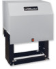
GLCONTROLLER BOARD MODEL SL575 HEAVY DUTY SLIDE GATE OPERATOR 2 YEAR WARRANTY Serial located on electrical box cover) Installation Date MODEL SL575 IS FOR VEHICULAR PASSAGE GATES ONLY AND IS NOT INTENDED FOR PEDESTRIAN PASSAGE GATE USE - LiftMaster SL575 | SL575 Manual - Page 2
K77-34846 Control Board Programming and Features 24-25 AVER Troubleshooting 26-27 Description Qty. Self-Regulating Heater Accessory 28 Safety Gate Brochure 1 Heater Wiring Diagram for 115, 208, 230, 460 Gate Bracket 2 and 575V Operators 28 Nickel Plated Chain #50 1 Single Phase - LiftMaster SL575 | SL575 Manual - Page 3
OPERATOR DIMENSIONS AND HORSEPOWER CHART MODEL SL575 • 1/2 HP Motor Maximum Cycle Rate - 22 cycles per hour (At Maximum Gate Weight) Maximum Gate Speed - 10"/sec. (25.4 cm/sec.) Maximum Gate Weight - 1200 lbs. (544.3 kg) Maximum Cantilever Gate Width - 25 ft. (7.6 m) Maximum Overhead Roller Gate - LiftMaster SL575 | SL575 Manual - Page 4
UL325 MODEL CLASSIFICATIONS CLASS I - RESIDENTIAL VEHICULAR GATE OPERATOR A vehicular gate operator (or system) intended for use in a home of one-to four single family dwellings, or a garage or parking area associated therewith. CLASS II - COMMERCIAL/GENERAL ACCESS VEHICULAR GATE OPERATOR A - LiftMaster SL575 | SL575 Manual - Page 5
Rollers • Vertical Posts • Photoelectric Sensors • Instructional and Precautionary Signage 4. Install the gate operator only when: a. The operator is appropriate for the construction and the usage class of the gate. b. All openings of a horizontal slide gate are guarded or screened from the bottom - LiftMaster SL575 | SL575 Manual - Page 6
SUGGESTED ENTRAPMENT PROTECTION DEVICE LOCATIONS GATE SYSTEM (MASTER/SECOND SLIDE GATE) Open Edge Gate 2 Open Edge STREET Photo eyes for close cycle Gate 1 Close Edge Photo eyes for open cycle Run twisted wire from loop to operator Interrupt (Safety) Loop 4'T(y1p.2icmal) 4'T(y1p.2icmal) - LiftMaster SL575 | SL575 Manual - Page 7
eyes MUST protect during both open and close gate cycles. Always Test Gate Edges and Photo Beams Anytime They Are AVERTISSEMENT • Injuries occur when people put their hands and arms through openings in the grill while the gate is operating. Adjusted or Serviced They cannot retract their arm - LiftMaster SL575 | SL575 Manual - Page 8
unit may be returned to service. AVERTISSEMENT • Disconnect power at the fuse box BEFORE proceeding. Operator MUST be properly grounded and and/or damage to operator. POWER WIARITNGTIENSNTATLLIAOTINON Wiring Specifications (STRANDED COPPER WIRE) AVERTISSEMENT On a Dual Gate System, each unit - LiftMaster SL575 | SL575 Manual - Page 9
cm) 21-1/8" (53.7 cm) 36" (91.4 cm) Concrete Anchor Holes Using Suitable Hardware To Secure Operator To Concrete Anchors Concrete Pad 1/2" Concrete Anchors (4 Required) 9 Drive and Idler Sprocket Toward Gate Side Power and Control Wiring Should Be Run In Separate Conduit 2" to 4" (5.1 to 10.2 cm - LiftMaster SL575 | SL575 Manual - Page 10
made of 3" (7.6 cm) outer diameter heavy walled pipe. Posts should be parallel and square to the gate (Figure 2). 2. Locate electrical conduit, as required, prior to pouring concrete. 3. Secure operator (Figure 3) to posts using four 3" (7.6 cm) U-bolts and hardware provided. 26" (66 cm) Post to - LiftMaster SL575 | SL575 Manual - Page 11
brackets to the vertical front and rear posts of the gate (Figure 1). 2. Remove the operator cover. 2" (5.1 cm) U-bolts AVERTISSEMENT 3. Locate and engage the manual disconnect and lock it in place with Lock Washers and Nuts (refer to page 12). 4. Connect chain take-up bolt to the end of the - LiftMaster SL575 | SL575 Manual - Page 12
the tension on the drive chain before disengaging the system. MODEL SL575 DISENGAGEMENT: Pull the disconnect chain and engage it A in the slot provided. The gate may now be moved manually. RE-ENGAGEMENT: Release the chain from the slot. (Some operator output sprocket rotation may be required - LiftMaster SL575 | SL575 Manual - Page 13
observe the operator's behavior. The gate should begin opening. If the operator fails to open or has difficulty opening, refer to the troubleshooting section. 5. Once at the open limit, the gate will stop. Push the close button and observe the operator's behavior. If the operator fails to close or - LiftMaster SL575 | SL575 Manual - Page 14
force. On most operators this will be around the middle of the range. SECONDARY ENTRAPMENT PROTECTION ADJUSTMENTS Terminals 9 & 5 - Obstruction While Opening (Edge/Photo Eye Input) Edge Input: See Programming Section on page 15. This input will reverse an opening gate to the close limit. Activating - LiftMaster SL575 | SL575 Manual - Page 15
the input functions to pause the gate during the opening cycle. Once the input is cleared the gate continues to open. Shown as factory default. Open Edge: When the control board is configured for safety edges, the input functions to reverse the gate to the close limit when the edge is activated - LiftMaster SL575 | SL575 Manual - Page 16
/SWING This switch selects slide or swing gate operation, in order to optimize gate behavior for specific application. SL = Slide • SW = Swing TTC SW TIMER-TO-CLOSE SWING GATE S1 ON ON 1 2 34 RT SAVE LT SL RIGHT/LEFT OPERATION This switch selects the gate opening direction, to the left or - LiftMaster SL575 | SL575 Manual - Page 17
come into contact with the gate while operating the controls where the user has full view of gate operation. *We strongly recommend that you follow the UL guidelines presented throughout the manual. Installation device instructions: Always follow the instructions provided by the manufacturer when - LiftMaster SL575 | SL575 Manual - Page 18
throughout the manual. Refer to instructions shipped with optional control devices for mounting, wiring, programming and adjustment. When using a remote control or Single Button Control Station in lieu of the Soft Open feature, perform the following modifications to the operator: 1. Remove the - LiftMaster SL575 | SL575 Manual - Page 19
the hand-held remote that you wish to operate your gate operator. The opener will now operate when the push button on either the receiver or the remote control is pressed. Repeat Steps 2 and 3 for each remote control that will be used to operate the gate operator. TO ERASE ALL REMOTE CONTROL CODES - LiftMaster SL575 | SL575 Manual - Page 20
is primarily used on swing gate operators. This input protects cars by preventing the gate from moving off of the open or close limit when the shadow loop a normally close stop circuit for proper system operation. After Master/Second wiring has been completed and the S4 switch programmed, both units - LiftMaster SL575 | SL575 Manual - Page 21
. Although nothing can absorb the tremendous power of a direct lightning strike, proper grounding can protect the gate operator in most cases. The earth ground rod must be located within 3 feet from the gate operator. Use the proper type earth ground rod for your local area. The ground wire must be - LiftMaster SL575 | SL575 Manual - Page 22
-Close will automatically close and secure the gate. SAMS OPERATION 1. When an authorized vehicle accesses the gate system, the SAM system responds by first opening the gate farthest from the vehicle, the swing or slide gate. 2. Once the swing or slide gate is open, the barrier gate begins its open - LiftMaster SL575 | SL575 Manual - Page 23
of travel, retest the gate operator. Failure to adjust and retest the gate operator properly can increase the risk of INJURY or DEATH. ATTENTION 5. Use the emergency release ONLY when the gate is not moving. 6. KEEP GATES PROPERLY MAINTAINED. Read the owner's manual. Have a qualified service person - LiftMaster SL575 | SL575 Manual - Page 24
be performed in stand alone mode. 1. Ensure that the operator remains attached to the gate throughout the entire process. 2. Press the motor learn button. The yellow LED should start to flash rapidly. 3. Push and hold down either the open or the close buttons. The motor will run for a few seconds - LiftMaster SL575 | SL575 Manual - Page 25
CONTROL BOARD PROGRAMMING AND FEATURES (CONTINUED) FORCE CONTROL Set the force control pot such that the unit will complete a full cycle of gate travel but can be reversed off an obstruction without applying an unreasonable amount of force. On most operators this will be around the middle of the - LiftMaster SL575 | SL575 Manual - Page 26
Problem in the motor 3) Problem in the contactor 4) Problem in the brake system 1) Failure to cycle power after setup 2) Communication wiring may be damaged or improperly wired for dual gate operation 3) Master or second unit is not programmed and test the operator. ➤ If the open or interrupt (safety - LiftMaster SL575 | SL575 Manual - Page 27
its travel without slipping but will slip when the gate hits an obstruction. ➤ Check belt for excessive wear. Belt can be adjusted by loosening the (4) mounting bolts securing motor to the frame and sliding motor until belt is taut. OPERATOR OPENS IMMEDIATELY UPON POWER UP AND DOES NOT CLOSE - LiftMaster SL575 | SL575 Manual - Page 28
Vac to operator controls Fusible de 3.2A Blue Yellow Grey (575V) Violet (480V) Orange (230V) Red (208V) White (Common) White (Common) Black (120V) Terminate unused transfer input wires Green Ground Black (N) Black (T1) HEATER REPLACEMENT PARTS PART NUMBER 21-15453-1 50-18423 DESCRIPTION - LiftMaster SL575 | SL575 Manual - Page 29
to brass screw, white wire to silver screw and green wire to green screw. 5) When using a remote control or Single Button Control Station in lieu of the Soft Open feature, perform the following modifications to the operator: 1. Remove the green wire from R4 of the radio block and mount the wire to - LiftMaster SL575 | SL575 Manual - Page 30
• DISCONNECT power BEFORE installing or servicing operator. • Replace ONLY with fuse AC"NC YEL/BLK L/S "BC"NC SHADOW CLOSE STOP OVERLOAD G J2 PLUG ON PCB RPM remote control or single button control station in lieu of the soft open feature, perform the following modific ations to the operator - LiftMaster SL575 | SL575 Manual - Page 31
pilot duty thermal overload device or an external line monitoring device. 4. When using a remote control or Single Button Control Station in lieu of the Soft Open feature, perform the following modifications to the operator: 1. Remove the green wire from R4 of the radio block and mount the wire - LiftMaster SL575 | SL575 Manual - Page 32
power BEFORE installing or servicing operator. BLACK (SL595 ORANGE) BRAKE SOLENOID RADIO SHADOW VDC COM CLOSE STOP SOFT OPEN HARD OPEN INTERRUPT YEL/BLK L/S "BC"NC remote control or single button control station in lieu of the soft open feature, perform the following modifications to the operator - LiftMaster SL575 | SL575 Manual - Page 33
AOMRON MODEL G65MG0204 G65MG0205 G65ME12C5 G65MGR205 G65MGS205 PHOTO-ELECTRIC CONTROLS DESCRIPTION Photocell/Electric Eye - 30' (9 m) Maximum Range SENSING EDGES DESCRIPTION Miller MG020 2-wire electric edge for gates. Sensitized on three sides. Requires mounting channel (4' [1.2 m] long). Miller - LiftMaster SL575 | SL575 Manual - Page 34
50-43, SL575-50-83 K20-3100B-4P Motor - models SL575-100-23, SL575-100-43, SL575-100-83 K20-3100M-5 Motor - model SL575-100-53 10 23-3001 23-3005 VARIABLE PARTS On/off switch - 1 phase 115 208/230V On/off switch - 3 phase 01-34851 01-34851SP 01-34851FR NOT SHOWN Owner's manual - English Owner - LiftMaster SL575 | SL575 Manual - Page 35
ILLUSTRATED PARTS K4 (K75-34842) 5 3 10 4 K3 (K75-34828) 9 8 7 K6 (K75-19977) K7 (K72-34844) K2 (K75-34824) K8 (K72-34845) K5 (K29-32410) 1 2 6 K1 (71-B120) (71-B208) (71-B240) (71-B575) K3 (K75-34828) 35 - LiftMaster SL575 | SL575 Manual - Page 36
nut Limit switch Contactor Open/close switch Transformer -115/208/230/460Vac/60VA Transformer - 575Vac/100VA Stop switch VARIABLE PARTS Overload - 6 AMP - SL575-50-21, SL575-50-81 Overload - 8 AMP - SL575-75-21, SL575-75-81, SL575-100-21, SL575-100-81 Overload - 10 AMP - SL575-50-11 Overload - 15 - LiftMaster SL575 | SL575 Manual - Page 37
NOTES 37 - LiftMaster SL575 | SL575 Manual - Page 38
NOTES 38 - LiftMaster SL575 | SL575 Manual - Page 39
NOTES 39 - LiftMaster SL575 | SL575 Manual - Page 40
AMERICA FOR INSTALLATION AND SERVICE INFORMATION, CALL OUR TOLL FREE NUMBER 1-800-528-2806 www.liftmaster.com WHEN ORDERING REPAIR PARTS PLEASE SUPPLY THE FOLLOWING INFORMATION: PART NUMBER DESCRIPTION MODEL NUMBER ADDRESS ORDER TO: THE CHAMBERLAIN GROUP, INC. Technical Support Group 6050 Country
-
 1
1 -
 2
2 -
 3
3 -
 4
4 -
 5
5 -
 6
6 -
 7
7 -
8
-
9
-
10
-
11
-
12
-
13
-
14
-
15
-
16
-
17
-
18
-
19
-
20
-
21
-
22
-
23
-
24
-
25
-
26
-
27
-
28
-
29
-
30
-
31
-
32
-
33
-
34
-
35
-
36
-
37
-
38
-
39
-
40
 |
 |

CONTROLLER BOARD
GL
Serial # ________________________
(located on electrical box cover)
Installation Date__________________
2 YEAR WARRANTY
MODEL SL575 IS FOR VEHICULAR PASSAGE
GATES ONLY AND IS NOT INTENDED FOR
PEDESTRIAN PASSAGE GATE USE
MODEL SL575
HEAVY DUTY SLIDE GATE OPERATOR