LiftMaster SL575 SL575 Manual - Page 12
Available Conduit Access For The Electrical Box, On/off Switch Power Wiring, Manual Disconnect - model
 |
View all LiftMaster SL575 manuals
Add to My Manuals
Save this manual to your list of manuals |
Page 12 highlights
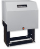
AVAILABLE CONDUIT ACCESS FOR THE ELECTRICAL BOX The accessory tray is equipped with several 1-1/2" pass though holes as well as 3/4" and 1" knock outs for conduit connectors. The electrical box is equipped with 3/4" and 1" knock outs for conduit connectors. ON/OFF SWITCH POWER WIRING NOTE: Before running power wiring refer to wiring specifications on page 8 for correct wire gauges. Secure all electrical power connections inside the disconnect switch electrical box. Refer to electrical wiring diagrams on pages 30 and 32. SINGLE PHASE All single phase 115V/208/230V operators will have the following: • L1 White • L2 Black • Ground, Green USE1C1O5PPVEROCOLNTDU1CTPORHO.NLY 115V SINGLE PHASE POWER SWITCH ASSEMBLY THREE PHASE All three phase operators will have the following: • L1 Black • L2 Black • L3 Black • Ground, Green USE1C1O5PPVEROCOLNTDU1CTPORHO.NLY 208/230V SINGLE PHASE & ALL THREE PHASE POWER SWITCH ASSEMBLY IMPORTANT NOTE: This operator is shipped from the factory as a right hand mounted unit, unit MUST be phased correctly. On three phase operators, power connections must be properly phased. If phased incorrectly, the gate operator will run reversed. To correct this situation, shut off power at main power source and at the operators electrical disconnect switch. Then reverse any two of the three power leads. MANUAL DISCONNECT NOTE: When the operator is under load, you may find it necessary to relieve the tension on the drive chain before disengaging the system. MODEL SL575 DISENGAGEMENT: Pull the disconnect chain and engage it A in the slot provided. The gate may now be moved manually. RE-ENGAGEMENT: Release the chain from the slot. (Some operator output sprocket rotation may be required for engagement.) Cable Stop Slot to Hold Cable Stop 12
-
 1
1 -
2
-
3
-
4
-
5
-
6
-
 7
7 -
 8
8 -
 9
9 -
 10
10 -
 11
11 -
 12
12 -
 13
13 -
 14
14 -
 15
15 -
 16
16 -
 17
17 -
18
-
19
-
20
-
21
-
22
-
23
-
24
-
25
-
26
-
27
-
28
-
29
-
30
-
31
-
32
-
33
-
34
-
35
-
36
-
37
-
38
-
39
-
40
 |
 |
