LiftMaster TAC2C TAC2C Installation Manual - Page 2
Testing - chamberlain
 |
View all LiftMaster TAC2C manuals
Add to My Manuals
Save this manual to your list of manuals |
Page 2 highlights
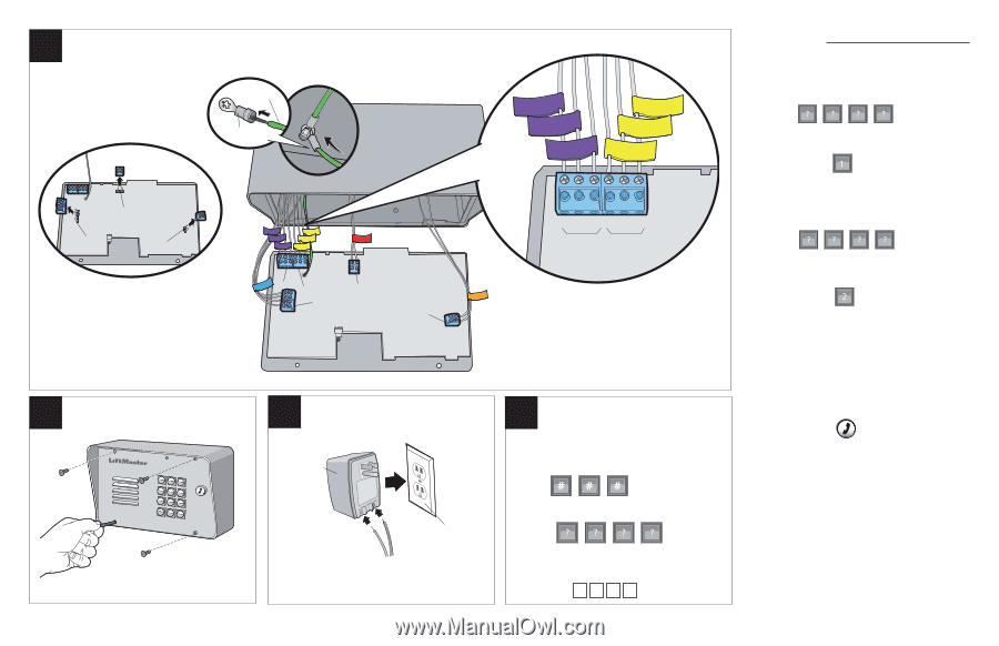
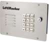
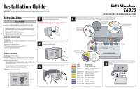
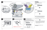
6 Attach the labeled wires to the new TAC2C board as shown. Crimp the ground lug onto the end of the ground wire on the new board. Attach the ground lug to the ground screw in the existing housing. Ground Wire Remove the PHONE, POWER, and AUTOCALL terminal blocks from the new board. Leave the Relay 1 and 2 terminal blocks. Ground Lug Ground Screw in existing housing Rewire the relay 1 and 2 wires to the relay 1 and 2 terminal blocks on the new board. RELAY 1 NC RELAY 1 NO RELAY 1 COM RELAY 2 COM RELAY 2 NO RELAY 2 NC Testing TEST GATE / DOOR RELAYS Test Relay 1 1 Enter 4 digit Master Code. 2 Press 1 to test Relay 1. POWER PHONE/TELCO AUTOCALL 7 When wiring is complete, secure the new faceplate to the existing housing with the provided screws (4). 1 23 456 789 *0# 01-35895B COM NO NC COM NO NC RELAY 1 RELAY 2 Test Relay 2 1 Enter 4 digit Master Code. RELAY 1 RELAY 2 POWER PHONE/TELCO NEW TAC2C BOARD AUTOCALL 2 Press 2 to test Relay 2. 8 Connect the power wires to the new transformer and plug the transformer into a 110 Vac outlet ONLY, any other type of outlet will cause damage to the unit. NEW 16 Vdc Transformer (provided) 110 Vac Outlet ONLY IMPORTANT NOTE: DO NOT use the existing transformer, the provided transformer MUST be used instead. 9 SET THE MASTER CODE Once power is applied, the unit will begin to "click" to indicate that it is powered, and is waiting to be programmed for the unit's Master Code. The Master Code is used to unlock the programming functions of the unit. The Master Code should not be distributed as a User Code. 1 Enter on the unit's keypad. 2 Enter 4-digit Master Code. Example: 1234. "BEEP" "BEEP" 3 Write down the Master Code and store in a secure location. TEST THE TELEPHONE CONNECTIONS 1 Place a telephone call from the resident's telephone to verify the unit is operating properly, then hang up the phone. 2 Press the "Call" button on the unit's keypad. The telephone in the residence should ring. 3 To test Relay 1 have someone answer the telephone and enter "*9" (Star + 9) to activate Relay 1. The unit will disconnect the call as soon as the relay is activated. To test Relay 2 have someone answer the telephone and enter "*5" (Star + 5). Relay 2 should activate. The unit will disconnect the call as soon as the relay is activated. For complete programming information refer to the Programming Guide. © 2011, The Chamberlain Group All Rights Reserved
-
 1
1 -
 2
2
 |
 |