Linksys SD208 Cisco SD205, SD208, SD216 10/100 Switches Quick Start Guide - Page 5
Connecting the 10/100 Switch - switch configuration
 |
UPC - 745883556823
View all Linksys SD208 manuals
Add to My Manuals
Save this manual to your list of manuals |
Page 5 highlights
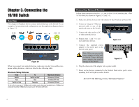
Chapter 3: Connecting the 10/100 Switch Planning Your Network Layout Overview This chapter will explain how to connect network devices to the Switch. For an example of a typical network configuration, see the application diagram shown in Figure 3-1. Figure 3-1 When you connect your network devices, make sure you don't exceed the maximum cabling distances, which are listed in the following table: Maximum Cabling Distances From Switch Hub Switch or Hub To Switch or Hub* Hub Computer Maximum Distance 100 meters (328 feet) 1 5 meters (16.4 feet) 1 100 meters (328 feet) 1 *A hub refers to any type of 100Mbps hub, including regular hubs and stackable hubs. A 10Mbps hub connected to another 10Mbps hub can span up to 100 meters (328 feet). 4 Connecting Network Devices Follow these instructions for the 5-, 8-, and 16-Port 10/100 Switches (the 5-Port 10/100 Switch is shown in Figures 3-2 and 3-3). 1. Make sure all the devices you will connect to the Switch are powered off. 2. Connect a Category 5 Ethernet network cable to one of the numbered ports on the Switch. 3. Connect the other end to a PC or other network device. 4. Repeat steps 2 and 3 to connect additional devices. Figure 3-2 5. Connect the supplied power adapter to the power port on the Switch's side panel. Note: Make sure you use the power adapter included with the Switch. Using a different power adapter may result in damage to the Switch. Figure 3-3 6. Plug the other end of the adapter into a power outlet. 7. Power on the devices connected to the Switch. Each active port's corresponding LED will light up on the Switch. Proceed to the following section, "Placement Options." 5
-
 1
1 -
 2
2 -
 3
3 -
 4
4 -
 5
5 -
 6
6 -
 7
7 -
 8
8 -
 9
9
 |
 |
