Linksys WRV210 Cisco Small Business WRV210 Administration Guide - Page 11
Verifying the Hardware Installation, Introduction, Front Panel, Appendix B - problems
 |
UPC - 745883582303
View all Linksys WRV210 manuals
Add to My Manuals
Save this manual to your list of manuals |
Page 11 highlights
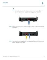
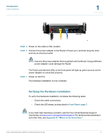
Introduction Initial Installation 1 STEP 5 Power on the cable or DSL modem. STEP 6 Connect the power adapter to the Router's Power port, and then plug the other end into an electrical outlet. NOTE Use only the power adapter that is supplied with the Router. Using a different power adapter could damage the Router. The Power and Internet LEDs on the front panel will light up green as soon as the power adapter is connected properly. STEP 7 Power on the PCs. The hardware installation is now complete. Verifying the Hardware Installation To verify the hardware installation, complete the following tasks: • Check the cable connections. • Check the LED states, as described in Front Panel, page 7. NOTE If you need help resolving a problem, visit the Cisco Small Business Support Community at www.cisco.com/go/smallbizsupport. For technical documentation and other links, see Appendix B, "Where to Go From Here." Cisco Small Business WRV210 Administration Guide 11
-
 1
1 -
2
-
3
-
4
-
5
-
 6
6 -
 7
7 -
 8
8 -
 9
9 -
 10
10 -
 11
11 -
 12
12 -
 13
13 -
 14
14 -
 15
15 -
 16
16 -
17
-
18
-
19
-
20
-
21
-
22
-
23
-
24
-
25
-
26
-
27
-
28
-
29
-
30
-
31
-
32
-
33
-
34
-
35
-
36
-
37
-
38
-
39
-
40
-
41
-
42
-
43
-
44
-
45
-
46
-
47
-
48
-
49
-
50
-
51
-
52
-
53
-
54
-
55
-
56
-
57
-
58
-
59
-
60
-
61
-
62
-
63
-
64
-
65
-
66
-
67
-
68
-
69
-
70
-
71
-
72
-
73
-
74
-
75
-
76
-
77
-
78
-
79
-
80
-
81
-
82
-
83
-
84
-
85
-
86
-
87
-
88
-
89
-
90
-
91
-
92
-
93
-
94
-
95
-
96
-
97
-
98
-
99
-
100
-
101
-
102
-
103
-
104
-
105
-
106
-
107
 |
 |
