Lowrance HDS-12 LIVE HDS Live Installation Manual - Page 21
Power and NMEA 0183 cable, Accessory wake up, Description, Color
 |
View all Lowrance HDS-12 LIVE manuals
Add to My Manuals
Save this manual to your list of manuals |
Page 21 highlights
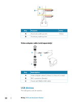
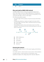
Power and NMEA 0183 cable A BD C E F G H I Key Description A + 12 V DC B DC negative C Fuse D Accessory wake up E Talker A (Tx_A) F Talker B (Tx_B) G Listener A (Rx_A) H Listener B (Rx_B) I Ground (shield) Color Red Black -Yellow Yellow Blue Orange Green -- Accessory wake up The accessory wake up wire may be used to control the power state of external equipment. Combine all accessory wake up wires on a common bus or to a single termination point. When connected in this manner, the connected equipment will turn on the moment the unit is powered up. Wiring | HDS Live Installation Manual 21
-
 1
1 -
2
-
3
-
4
-
5
-
6
-
7
-
8
-
9
-
10
-
11
-
12
-
13
-
14
-
15
-
 16
16 -
 17
17 -
 18
18 -
 19
19 -
 20
20 -
 21
21 -
 22
22 -
 23
23 -
 24
24 -
 25
25 -
 26
26 -
27
-
28
-
29
-
30
-
31
-
32
-
33
-
34
-
35
-
36
-
37
-
38
-
39
-
40
-
41
-
42
-
43
-
44
-
45
-
46
-
47
-
48
-
49
-
50
-
51
-
52
-
53
-
54
-
55
-
56
-
57
-
58
-
59
-
60
-
61
-
62
-
63
-
64
-
65
-
66
-
67
-
68
-
69
-
70
 |
 |

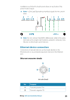
Power and NMEA 0183 cable
E
F
G
H
I
A
B
C
D
Key
Description
Color
A
+ 12 V DC
Red
B
DC negative
Black
C
Fuse
--
D
Accessory wake up
Yellow
E
Talker A (Tx_A)
Yellow
F
Talker B (Tx_B)
Blue
G
Listener A (Rx_A)
Orange
H
Listener B (Rx_B)
Green
I
Ground (shield)
--
Accessory wake up
The accessory wake up wire may be used to control the power state
of external equipment. Combine all accessory wake up wires on a
common bus or to a single termination point. When connected in
this manner, the connected equipment will turn on the moment
the unit is powered up.
Wiring
| HDS Live Installation Manual
21