MSI G31M3-L V2 User Guide - Page 11
Installing Memory Modules - bios
 |
UPC - 816909046557
View all MSI G31M3-L V2 manuals
Add to My Manuals
Save this manual to your list of manuals |
Page 11 highlights
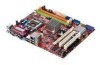
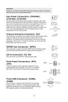
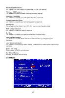
on the edge of the CPU base. Note that the alignment keys are matched. 7. Visually inspect if the CPU is seated well into the socket. If not, take out the CPU with pure vertical motion and reinstall. 8. Cover the load plate onto the package. 9. Press down the load lever lightly onto the load plate, and then secure the lever with the hook under retention tab. 10. Align the holes on the mainboard with the cooler. Push down the cooler until its four clips get wedged into the holes of the mainboard. 11. Press the four hooks down to fasten the cooler. Then rotate the locking switch (refer to the correct direction marked on it) to lock the hooks. 12. Turn over the mainboard to confirm that the clip-ends are correctly inserted. Important: Read the CPU status in BIOS. Whenever CPU is not installed, always protect your CPU socket pin with the plastic cap covered to avoid damaging. Mainboard photos shown in this section are for demonstration of the CPU/cooler installation only. The appearance of your mainboard may vary depending on the model you purchase. Installing Memory Modules 1. The memory module has only one notch on the center and will only fit in the right orientation. 2. Insert the memory module vertically into the DIMM slot. Then push it in until the golden finger on the memory module is deeply inserted in the DIMM slot. You can barely see the golden finger if the memory module is properly inserted in the DIMM slot. The plastic clip at each side of the DIMM slot will automatically close when the memory module is properly seated. 3. Manually check if the memory module has been locked in place by the DIMM slot clips at the sides. Notch Vo l t 5
-
 1
1 -
2
-
3
-
4
-
5
-
 6
6 -
 7
7 -
 8
8 -
 9
9 -
 10
10 -
 11
11 -
 12
12 -
 13
13 -
 14
14 -
 15
15 -
 16
16 -
17
-
18
-
19
-
20
-
21
-
22
-
23
-
24
-
25
-
26
-
27
-
28
-
29
-
30
-
31
-
32
-
33
-
34
-
35
-
36
-
37
-
38
-
39
-
40
-
41
-
42
-
43
-
44
-
45
-
46
-
47
-
48
-
49
-
50
-
51
-
52
-
53
-
54
-
55
-
56
-
57
-
58
-
59
-
60
-
61
-
62
-
63
-
64
-
65
-
66
-
67
-
68
-
69
-
70
-
71
-
72
-
73
-
74
-
75
-
76
-
77
-
78
-
79
-
80
-
81
-
82
-
83
-
84
-
85
-
86
-
87
-
88
-
89
-
90
-
91
-
92
-
93
-
94
-
95
 |
 |
