MSI H81M User Guide - Page 22
Front Panel I/O Connectivity Design Guide.
 |
View all MSI H81M manuals
Add to My Manuals
Save this manual to your list of manuals |
Page 22 highlights
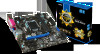
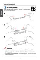
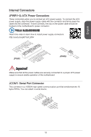
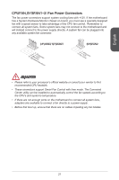
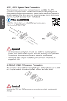
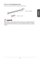
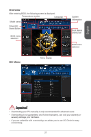
English JFP1, JFP2: System Panel Connectors These connectors connect to the front panel switches and LEDs. The JFP1 connector is compliant with the Intel® Front Panel I/O Connectivity Design Guide. When installing the front panel connectors, please use the optional M-Connector to simplify installation. Plug all the wires from the computer case into the M-Connector and then plug the M-Connector into the motherboard. Video Demonstration Watch the video to learn how to Install front panel connectors. http://youtu.be/DPELIdVNZUI PowPoewr LeEr DSwi2tc.h+41.0-6..N+8o.-Pin JFP1 1.+3.-5.-7.H+9D.RDReLseEesDrevteSdwitch JFP2 1.S2p.V3eC.aS4kCp.eV5erCakCe5r Important • On the connectors coming from the case, pins marked by small triangles are positive wires. Please use the diagrams above and the writing on the optional MConnectors to determine correct connector orientation and placement. • The majority of the computer case's front panel connectors will primarily be plugged into JFP1. JUSB1~2: USB 2.0 Expansion Connectors This connector is designed for connecting high-speed USB peripherals such as USB HDDs, digital cameras, MP3 players, printers, modems, and many others. 2.V4C.U6C.SU8BS1.1G0B-r.1No+uCnd 1.V3C.U5CS.U7BS.0G9B-.rN0o+ounPdin Important Note that the VCC and GND pins must be connected correctly to avoid possible damage. 22
-
 1
1 -
2
-
3
-
4
-
5
-
6
-
7
-
8
-
9
-
10
-
11
-
12
-
13
-
14
-
15
-
16
-
 17
17 -
 18
18 -
 19
19 -
 20
20 -
 21
21 -
 22
22 -
 23
23 -
 24
24 -
 25
25 -
 26
26 -
 27
27 -
28
-
29
-
30
-
31
-
32
-
33
-
34
-
35
-
36
-
37
-
38
-
39
-
40
-
41
-
42
-
43
-
44
-
45
-
46
-
47
-
48
-
49
-
50
-
51
-
52
-
53
-
54
-
55
-
56
-
57
-
58
-
59
-
60
-
61
-
62
-
63
-
64
-
65
-
66
-
67
-
68
-
69
-
70
-
71
-
72
-
73
-
74
-
75
-
76
-
77
-
78
-
79
-
80
-
81
-
82
-
83
-
84
-
85
-
86
-
87
-
88
-
89
-
90
-
91
-
92
-
93
-
94
-
95
-
96
-
97
-
98
-
99
-
100
-
101
-
102
-
103
-
104
-
105
-
106
-
107
-
108
-
109
-
110
-
111
-
112
-
113
-
114
-
115
-
116
-
117
-
118
-
119
-
120
-
121
-
122
-
123
-
124
-
125
-
126
-
127
-
128
-
129
-
130
-
131
-
132
-
133
-
134
-
135
-
136
-
137
-
138
-
139
-
140
-
141
-
142
-
143
-
144
-
145
-
146
-
147
-
148
-
149
-
150
-
151
-
152
-
153
-
154
-
155
-
156
-
157
-
158
-
159
-
160
-
161
-
162
-
163
-
164
-
165
-
166
-
167
-
168
-
169
-
170
-
171
-
172
-
173
-
174
-
175
-
176
-
177
-
178
-
179
-
180
-
181
-
182
-
183
-
184
-
185
-
186
 |
 |