MSI K7T266 User Guide
MSI K7T266 - PRO-R Motherboard - ATX Manual
 |
View all MSI K7T266 manuals
Add to My Manuals
Save this manual to your list of manuals |
MSI K7T266 manual content summary:
- MSI K7T266 | User Guide - Page 1
MSI K7T266 Pro2 Series MICRO-STAR INTERNATIONAL MS-6380 ATX Mainboard Version 2.1 G52-MA00434 i - MSI K7T266 | User Guide - Page 2
and used in accordance with the instruction manual, may cause harmful interference to radio approved by the party responsible for compliance could void the user's authority to operate the equipment. Notice 2 Shielded interface MS-6380 Tested to comply with FCC Standard For Home or Office Use ii - MSI K7T266 | User Guide - Page 3
. Our products are under continual improvement and we reserve the right to make changes without notice. Trademarks All trademarks used in this manual are the property of their respective owners. AMD, Athlon and Duron are registered trademarks of AMD Corporation. PS/2 and OS/2 are registered - MSI K7T266 | User Guide - Page 4
1. Always read the safety instructions carefully. 2. Keep this User's Manual for future reference. 3. Keep this equipment away . 11. If any of the following situations arises, get the equipment checked by a service personnel: z The power cord or plug is damaged z Liquid has penetrated into the - MSI K7T266 | User Guide - Page 5
MSI Special Features 1-10 PC Alert™ III 1-10 Fuzzy Logic™ III 1-12 D-LED™ (Optional) & D-Bracket 1-13 Chapter 2. Hardware Setup 2-1 Central Processing Unit: CPU 2-2 CPU Installation Procedures 2-2 CPU Core Speed Derivation Procedure 2-4 CPU Clock Frequency Selection through BIOS 2-4 Memory - MSI K7T266 | User Guide - Page 6
Pro2-R, K7T266 Pro2RU 2-19 Chassis Intrusion Switch Connector: J3 2-20 CD-In/Aux Line-In/Modem-In Connector: JCD/JAUX/JMDM ... 2-21 Fan Power Connectors: CFAN1/SFAN1/PSFAN1 2-22 Front USB Request Routing 2-31 Chapter 3. AMI® BIOS Setup 3-1 Entering Setup 3-2 Selecting the First Boot Device 3-2 - MSI K7T266 | User Guide - Page 7
/BIOS Setup Defaults 3-29 Supervisor/User Password Drivers 4-1 Driver Installation for Windows® 98SE 4-2 Driver Installation for Windows® 2000 4-3 Driver Installation for Windows® ME 4-4 Driver Installation for Windows® NT4.0 4-5 Appendix.MSISmartKey A-1 Installing MSI Smart Key A-2 Using MSI - MSI K7T266 | User Guide - Page 8
The K7T266 Pro2 (MS-6380 v2.X) series K7T266 Pro2 series motherboards. They are K7T266 Pro2, K7T266 Pro2-R, K7T266 Pro2-U and K7T266 Pro2-RU. K7T266 Pro2 is the standard version. In addition to standard features, K7T266 Pro2-R adds support for IDE RAID function, while K7T266 Pro2-U does not support - MSI K7T266 | User Guide - Page 9
Ethernet LPC - Integrated Hardware Sound Blaster/Direct Sound AC97 audio - Ultra DMA 33/66/100 master mode PCI EIDE controller - ACPI Clock Generator z 100/133MHz clocks are supported. Main Memory z Supports six memory banks using three 184-pin DDR DIMMs z Supports a maximum memory size up to 3GB - MSI K7T266 | User Guide - Page 10
two hard disk drives will adopt RAID function. USB Interface z K7T266 Pro2-U, K7T266 Pro2-RU: 4 USB 2.0 ports, 4 USB 1.1 ports z K7T266 Pro2, K7T266 Pro2-R: 6 USB 1.1 ports Audio z Chip integrated (2 channel S/W audio) - Direct Sound AC97 Audio On-Board Peripherals z On-Board Peripherals include - MSI K7T266 | User Guide - Page 11
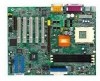
Chapter 1 Mainboard Layout Top : mouse Bottom: keyboard USB JKBV1 ports SOCKET 462 CFAN1 PSFAN1 ATX Power Supply 4 PCI Slot 5 DDR 1 DDR 2 DDR 3 VT8233 B AT T + BIOS JBAT1 SFAN1 JWOL1 JMDM1 J7 CNR JAUX JMDM JCD J12 JUSB2 JUSB3 JGL1 JFP1 K7T266 Pro2 ATX Mainboard (MS-6380 v2.X) 1-4 - MSI K7T266 | User Guide - Page 12
Introduction Top : mouse Bottom: keyboard USB JKBV1 ports SOCKET 462 CFAN1 PSFAN1 ATX Power Supply Top : JCD J12 JUSB2 JUSB3 DDR 1 DDR 2 DDR 3 B AT T + BIOS VT8233 P RO MI S E 20265R JBAT1 SFAN1 J6 IDE 4 IDE 3 JMDM1 J7 JWOL1 JGL1 JFP1 K7T266 Pro2-R ATX Mainboard (MS-6380 v2.X) 1-5 - MSI K7T266 | User Guide - Page 13
Chapter 1 Top : mouse Bottom: keyboard USB JKBV1 ports SOCKET 462 CFAN1 PSFAN1 ATX Power 5 DDR 1 DDR 2 DDR 3 VT8233 B AT T + BIOS JBAT1 SFAN1 JWOL1 JMDM1 J7 CNR JAUX JMDM JCD J12 JUSB1 JUSB2 JUSB3 NEC USB2.0 Host Controller JGL1 JFP1 K7T266 Pro2-U ATX Mainboard (MS-6380 v2.X) 1-6 - MSI K7T266 | User Guide - Page 14
Introduction Top : mouse Bottom: keyboard USB JKBV1 ports SOCKET 462 CFAN1 PSFAN1 ATX Power J12 JUSB1 JUSB2 JUSB3 B AT T + BIOS VT8233 P RO MI S E 20265R JBAT1 SFAN1 J6 IDE 4 NEC USB2.0 Host Controller IDE 3 JMDM1 J7 JWOL1 JFP1 JGL1 K7T266 Pro2-RU ATX Mainboard (MS-6380 v2.X) 1-7 - MSI K7T266 | User Guide - Page 15
Quick Components Guide Component Function Reference DDR1~3 Installing DDR SDRAM modules See p. 2-5~2-6 Socket 462 Installing CPU See p. FDD1 Connecting to floppy disk drive See p.2-12 JUSB1~3 Connecting to USB interfaces See p. 2-23~2-25 PCI Slot 1~5 Installing expansion cards See - MSI K7T266 | User Guide - Page 16
™/Athlon™/Athlon XP processor z Memory: 3 PC1600/PC2100 DDR DIMMs z Slot: 1 AGP slot, 1 CNR slot, 5 PCI slots z K7T266 Pro2 & K7T266 Pro2-R I/O: 2 serial ports. 1 parallel port, 6 USB 1.1 ports, 1 floppy port, 1 IrDA connector, 3 Audio/1 Game port z K7T266 Pro2-U & K7T266 Pro2-RU I/O: 2 serial ports - MSI K7T266 | User Guide - Page 17
MSI Special Features PC Alert™ III The PC AlertTM III is a utility you can find in the CD-ROM disk. The utility is just like your PC doctor that can detect the following PC hardware status during real time operation: * monitor CPU ,until user disables the warning. Note: Items shown on PC Alert - MSI K7T266 | User Guide - Page 18
Introduction Features: z Network Management - Monitoring & remote control z Basic System Utilities - Scandisk & Defragment to maintain your HDD z 3D Graphics Design - Enables a more friendly user interface z Sofware Utilities - SoftCooler Optimized Cooling 1-11 - MSI K7T266 | User Guide - Page 19
The Fuzzy Logic™ III utility allows users to overclock the CPU FSB (Front Side Bus) frequency in the Windows environment. Select the CPU frequency you prefer and click Go to Displays Current System Status - CPU Fan - CPU Temp. - Vcore - Vio - Memory Clock - CPU Clock - AGP Clock - PCI Clock z Adjusts - MSI K7T266 | User Guide - Page 20
up to 16 combinations of signals to 2 debug the system. The 4 LEDs can debug all problems that 3 fail the system, such as VGA, RAM or other failures. This special feature is very useful for the overclocking users. 4 These users can use the feature to detect if there are any Diagnostic LED - MSI K7T266 | User Guide - Page 21
and initialize the video adapter. BIOS Sign On - This will start showing information about logo, processor brand name, etc.... Testing Base and Extended Memory - Testing base memory from 240K to 640K and extended memory above 1MB using various patterns. Assign Resources to all ISA. Initializing - MSI K7T266 | User Guide - Page 22
properly. Use a grounded wrist strap before handling computer components. Static electricity may damage the components. This chapter contains the following topics: Central Processing Unit (CPU) 2-2 Memory 2-5 Power Supply 2-7 Back Panel 2-8 Connectors 2-12 Jumpers 2-27 Slots 2-30 2-1 - MSI K7T266 | User Guide - Page 23
Chapter 2 Central Processing Unit: CPU The mainboard supports AMD® AthlonTM, Athlon XP and DuronTM processors. It uses a CPU socket called Socket A for easy CPU installation. Make sure the CPU has a Heat Sink and a cooling fan attached on the top to prevent overheating. If you do not find the Heat - MSI K7T266 | User Guide - Page 24
a speed of 600MHz and above requires LARGER heatsink and fan. You also need to add thermal grease between the CPU and heatsink to improve heat dissipation. Then, make sure that the CPU and heatsink are securely fastened and in good contact with each other. These are needed to prevent damaging the - MSI K7T266 | User Guide - Page 25
the CPU clock in the BIOS Setup utility. WARNING! Replacing CPU While replacing the CPU, always turn off the ATX power supply or unplug the power cable of the ATX power supply from grounded outlet first to ensure the safety of CPU. Overclocking This motherboard is designed to support overclocking - MSI K7T266 | User Guide - Page 26
The mainboard provides 3 sockets for 184-pin unbuffered DDR DIMM (Double In-Line Memory Module) modules and supports a maximum memory size of 3GB. DDR DIMM Slots (DDR 1~3) Introduction to DDR SDRAM You can install PC1600/PC2100 DDR SDRAM modules on the DDR DIMM slots (DDR 1~3). - MSI K7T266 | User Guide - Page 27
DIMM Modules Combination At least one DIMM module should be installed on the motherboard. Memory modules can be installed on the slots in any order. The single-/ double-sided memory modules that each DIMM slot supports are listed as below: S (Single Side): 64MB ~ 512MB D (Double Side): 128MB ~ 1GB - MSI K7T266 | User Guide - Page 28
Hardware Setup Power Supply The mainboard supports ATX power supply for the power system. Before inserting the power supply connector, always make sure that all components are installed properly to ensure that - MSI K7T266 | User Guide - Page 29
Chapter 2 Back Panel The Back Panel provides the following connectors: Mouse Parallel Midi/Joystick Keyboard USB COM A COM B L-out L-in MIC Mouse Connector The mainboard provides a standard PS/2® mouse mini DIN connector for attaching a PS/2® mouse. You can plug a PS/2® mouse - MSI K7T266 | User Guide - Page 30
Host Controller Interface) Universal Serial Bus root for attaching USB devices such as keyboard, mouse or other USB-compatible devices. You can plug the USB device directly into ths connector. 1 2 3 4 5 6 7 8 USB Ports USB Port Description PIN SIGNAL 1 VCC 2 -Data 0 3 +Data0 4 GND 5 VCC - MSI K7T266 | User Guide - Page 31
2 Parallel Port Connector The mainboard provides a 25-pin female centronic connector for LPT. A parallel port is a standard printer port that supports Enhanced Parallel Port (EPP) and Extended Capabilities Parallel Port (ECP) mode. 13 1 25 14 Pin Definition PIN SIGNAL DESCRIPTION 1 STROBE - MSI K7T266 | User Guide - Page 32
) Ground Data Set Ready Request To Send Clear To Send Ring Indicate Joystick/Midi Connectors You can connect a joystick or game pad to this connector. Audio Port Connectors Line Out is to connect speakers or headphones. Line In is a connector for external CD player, Tape player or other - MSI K7T266 | User Guide - Page 33
The mainboard provides connectors to connect to FDD, IDE HDD, case, modem, USB Ports, IR module and CPU/Power supply/System FAN. Floppy Disk Drive Connector: FDD1 The mainboard provides a standard floppy disk drive connector that supports 360K, 720K, 1.2M, 1.44M and 2.88M floppy disk types. 34 33 - MSI K7T266 | User Guide - Page 34
the second drive to Slave mode by setting its jumper. Refer to the TIP hard disk documentation supplied by hard disk vendors for jumper setting instructions. 2-13 - MSI K7T266 | User Guide - Page 35
K7T266 Pro2-R, K7T266 Pro2-RU) The mainboard offers a low-cost RAID (Redundant Array of Independent Disks) solution by integrating two IDE RAID connectors that support connectors support hard disk drives only. - For more information on IDE RAID, please refer to IDE RAID Manual. ( instructions. 2-14 - MSI K7T266 | User Guide - Page 36
Hardware Setup Case Connector: JFP1 The case connector block JFP1 allows you to connect to the Power Switch, Reset Switch, Keylock, Speaker, Power LED, and HDD LED on the case. Keylock Buzzer (short pin) Speaker R e s e t Switch 14 15 + + HDD LED Power Power LED Switch JFP1 Power Switch - MSI K7T266 | User Guide - Page 37
Chapter 2 HDD LED HDD LED shows the activity of a hard disk drive connected to the IDE1 or IDE2 connector. Avoid turning the power off while the HDD is working. You can connect the HDD LED from the system case to this pin. Keylock Keylock allows you to disable the keyboard for security purpose. You - MSI K7T266 | User Guide - Page 38
Hardware Setup Power Saving LED Connector: JGL1 JGL1 is connected to a power saving LED. There are three types of LED that you can use: 3-pin/2-pin dual color or 2-pin single color LED. If connected to a dual color LED, the LED light is green when system in turned on, and turns to orange color while - MSI K7T266 | User Guide - Page 39
Chapter 2 Wake On LAN Connector: JWOL1 This connector allows you to connect to a LAN card with Wake On LAN function. You can wake up the computer via remote control through a local area network. 1 5VSB GND MP_WAKEUP JWOL1 Wake On Ring Connector: JMDM1 This connector allows you to connect to a - MSI K7T266 | User Guide - Page 40
to connect to an IrDA Infrared module. You must configure the setting through the BIOS setup to use the IR function. Pin Signal 1 VCC 2 NC 3 IRRX 4 GND 5 IRTX 1 J7 IDE RAID HDD LED Connector: J6 (K7T266 Pro2-R, K7T266 Pro2-RU) The connector is used to connect to a HDD LED for showing the activity of - MSI K7T266 | User Guide - Page 41
switch will be short. The system will record this status and show a warning message on the screen. To clear the warning, you must enter the BIOS utility and clear the record. J3 2-20 - MSI K7T266 | User Guide - Page 42
connector. JAUX connector is for DVD add-on card with Line-in connector. JMDM connector is for modem with internal audio connector. Phone_In GND Mono_Out JMDM L GND R JAUX L GND R JCD Note: Mono_Out is connected to the Modem speaker-out connector. Phone_In is connected to the Modem - MSI K7T266 | User Guide - Page 43
use a specially designed fan with speed sensor to take advantage of the CPU fan control. SENSOR +12V GND CFAN1 SENSOR +12V GND PSFAN1 SENSOR +12V GND SFAN1 Note: 1. Always consult the vendor for proper CPU cooling fan. 2. CPU Fan supports the fan control. You can install the PC Alert utility that - MSI K7T266 | User Guide - Page 44
Serial Bus) pin headers, that allow you to connect optional USB ports for front panel. Two USB Connectors: JUSB2 & JUSB3 (K7T266 Pro2, K7T266 Pro2-R) If your mainboard comes with two USB pin headers, these headers are compatible with USB 1.1 specification. Therefore, the mainboard can offer six - MSI K7T266 | User Guide - Page 45
2 THREE USB Connectors: JUSB1, JUSB2 & JUSB3 (K7T266 Pro2-U, K7T266 Pro2-RU) If your mainboard comes with three USB pin headers along with the NEC USB 2.0 controller, two of the headers comply with high-speed USB 2.0 specification and one is compliant to USB 1.1 specification. USB 2.0 technology - MSI K7T266 | User Guide - Page 46
the system case. Note: The USB 2.0 controller is backwards compatible with USB 1.1 spec. To use the USB 2.0 ports, you still need to install USB 2.0 driver, which is supplied by Microsoft for Windows® 2000 and XP. If you have any problems regarding USB 2.0 driver, please visit Microsoft website for - MSI K7T266 | User Guide - Page 47
Chapter 2 D-Bracket™ Connector: J4 The motherboard comes with J4 connector and you can connect a D- Bracket™ to J4. D-Bracket™ is a USB bracket integrating four LEDs whose functions are similar to D-LED™ and allows users to identify system problem through 16 various combinations of LED signals. For - MSI K7T266 | User Guide - Page 48
your motherboard's function through the use of jumpers. Clear CMOS Jumper: JBAT1 There is a CMOS RAM on RAM, the system can automatically boot OS every time it is turned on. If you want to clear the system configuration, use the JBAT1 (Clear CMOS Jumper ) to clear data. Follow the instructions - MSI K7T266 | User Guide - Page 49
Wake-up Jumper: JKBV1 The JKBV1 jumper is used to set PS/2 keyboard/mouse and Rear USB wake-up function. To use the function, you should also go to BIOS to enable the PS/2 keyboard/mouse & USB wake-up (power on) function. 1 JKBV1 3 1 VCC 5V -Disable Keyboard Power On Function 3 1 5V StandBy - MSI K7T266 | User Guide - Page 50
device wake-up function. To use the function, you should also go to BIOS to enable the USB wake-up (power on) function. 1 J12 1 3 5V StandBy (Default)-Enable Front USB Wake Up Function 1 3 VCC 5V -Disable Front USB Wake Up Function Note: To be able to use this function, you need a power supply - MSI K7T266 | User Guide - Page 51
Slots The motherboard provides one 66MHz, 32-bit channel for the graphics controller to directly access main memory and provides three levels of throughputs: 1x (266Mbps), 2x (533Mbps) the expansion card, such as jumpers, switches or BIOS configuration. CNR (Communication Network Riser) The CNR - MSI K7T266 | User Guide - Page 52
microprocessor. To install a PCI expansion card on a PCI shared slot, you must make sure the card's driver supports "IRQ shared" function or there is no need to assign an IRQ to the device. The "AGP/PCI/USB/Promise ATA100" IRQ pins are typically connected to the PCI bus INTA#-INTD# pins as follows - MSI K7T266 | User Guide - Page 53
Setup Chapter 3. AMI® BIOS Setup AMI® BIOS Setup 3 The mainboard uses AMI® BIOS ROM that provides a Setup utility for users to modify the basic system configuration. The information is stored in a battery-backed CMOS RAM so it retains the Setup information when the power is turned off. The - MSI K7T266 | User Guide - Page 54
simultaneously pressing , , and keys. Selecting the First Boot Device You are allowed to select the 1st boot device without entering the BIOS setup utility by pressing . When the same message as listed above appears on the screen, press to trigger the boot menu. The - MSI K7T266 | User Guide - Page 55
changes Restore the previous CMOS value from CMOS, only for Option Page Setup Menu Load High Performance defaults, only for Option Page Setup Menu Load BIOS Setup defaults Save all the CMOS changes and exit Getting Help After entering the Setup utility, the first screen you see is the Main Menu - MSI K7T266 | User Guide - Page 56
items and press to enter the sub-menu. Standard CMOS Features Use this menu for basic system configurations, such as time, date etc. Advanced BIOS Features Use this menu to setup the items of AMI® special enhanced features. Advanced Chipset Features Use this menu to change the values in the - MSI K7T266 | User Guide - Page 57
Setup Defaults Use this menu to load factory default settings into the BIOS for stable system performance operations. Supervisor Password Use this menu to set Supervisor Password. User Password Use this menu to set User Password. Save & Exit Setup Save changes to CMOS and exit setup. Exit Without - MSI K7T266 | User Guide - Page 58
. day Day of the week, from Sun to Sat, determined by BIOS. Read-only. month The month from Jan. through Dec. date The date from 1 keyed by numeric function keys. year The year can be adjusted by users. Time This allows you to set the system time that you want (usually the - MSI K7T266 | User Guide - Page 59
and 2.88 MB 3½. Boot Sector Virus Protection The item is to set the Virus Warning feature for IDE Hard Disk boot sector protection. When Enabled, BIOS will issue a virus warning message and beep if a write to the boot sector or the partition table of the HDD is attempted. Setting options: Disabled - MSI K7T266 | User Guide - Page 60
Chapter 3 Advanced BIOS Features Quick Boot Setting the item to Enabled allows the system to boot within 5 seconds since it will skip some check items. Available options: Enabled - MSI K7T266 | User Guide - Page 61
. The system will boot from the third BBS (BIOS Boot Specification) compliant device. The system will boot from the fourth BBS (BIOS Boot Specification) compliant device. Disable this sequence. Note system is powered on. Setting to Off will allow end users to use the arrow keys on the numeric 3-9 - MSI K7T266 | User Guide - Page 62
setting causes the BIOS to search for floppy disk drives at boot time. When enabled, the BIOS will activate the password prompt appears only when end users try to run Setup. Always A Cache memory is additional memory that is much faster than conventional DRAM (system memory). When the CPU requests - MSI K7T266 | User Guide - Page 63
mode will expand available IRQs resources for the system. Settings: Enabled and Disabled. MPS Table Version This field allows you to select which MPS (Multi-Processor Specification) version to be used for the operating system. You need to select the MPS version supported by your operating system. To - MSI K7T266 | User Guide - Page 64
Time, RAS Pulse Width, RAS to CAS Delay and Bank Interleave automatically to be determined by BIOS based on the configurations on the SPD. Selecting User allows user to configure these fields manually. SDRAM Frequency Use this item to configure the clock frequency of the installed SDRAM. Settings - MSI K7T266 | User Guide - Page 65
AMI® BIOS Setup DRAM clock will be 100MH SPD SPD will set the clock frequency by reading the contents of the SPD device. When the installed CPU is 100MHz, this field has three setting options: HCLK, HCLK+33 and SPD. When the installed one is 133MHz, the three setting options will become - MSI K7T266 | User Guide - Page 66
memory CPU to handle data/instructions at a faster speed. AGP Mode The item sets an appropriate mode for the installed AGP card. Settngs are 1x, 2x, 4x and Auto. Select 4x only if your AGP card can support it. AGP Comp. Driving This filed is used to adjust the AGP driving force. Selecting Manual - MSI K7T266 | User Guide - Page 67
Disabled. Search for MDA Resources MDA stands for Mono Display support delayed transactions cycles. Select Enabled to support compliance with PCI specification version 2.1. Settings: Enabled and Disabled. BIOS Protection This function protects the BIOS from accidental corruption by unauthorized users - MSI K7T266 | User Guide - Page 68
Chapter 3 Protection function. You should enable this function at all times. The only time when you need to disable it is when you want to update the BIOS. After updating the BIOS, you should immediately re-enable it to protect it against viruses. Settings: Enabled and Disabled. 3-16 - MSI K7T266 | User Guide - Page 69
BIOS for ACPI function. If your operating system supports ACPI, such as Windows 98SE, Windows ME this state, no system context is lost (CPU or chipset) and hardware maintains all system memory and wake-capable devices and all system context is saved to main memory. The information stored in memory - MSI K7T266 | User Guide - Page 70
BIOS call VGA BIOS to initialize the VGA card when system wakes up (resume) from S3 state. The system resume time is shortened if you disable the function, but system will need AGP driver to initialize the card. Therefore, if the AGP driver of the VGA card does not support system resources allocated - MSI K7T266 | User Guide - Page 71
service required by the I/O device. CPU Critical Temperature This item is used to specify a thermal limit for CPU. If CPU temperature reaches the specified limit, the system will issue a warning to prevent the CPU overheat problem to install a modem/LAN card supporting power on function for Wake Up - MSI K7T266 | User Guide - Page 72
Chapter 3 Resume By Alarm This is used to enable or disable the feature of booting up the system on a scheduled time/date from the soft off (S5) state. Settings: Enabled and Disabled. Alarm Date/Hour/Minute/Second If Resume By Alarm is set to Enabled, the system will automatically resume (boot - MSI K7T266 | User Guide - Page 73
CPU itself uses when communicating with its special components. This section covers some very technical items and it is strongly recommended that only experienced users Data) NVRAM (Non-volatile Random Access Memory) is where the BIOS stores resource information for both PNP and non-PNP - MSI K7T266 | User Guide - Page 74
0/1/3/5/6/7 These items specify the bus that the system DMA (Direct Memory Access) channel is used. The settings determine if AMIBIOS should remove the system BIOS. The available DMA pool is determined by reading the ESCD NVRAM. If more DMAs must be removed from the pool, the end user can reserve - MSI K7T266 | User Guide - Page 75
FDC Function This is used to enable or disable the onboard Floppy controller. Option Auto Enabled Disabled Description BIOS will automatically determine whether to enable the onboard Floppy controller or not. Enables the onboard Floppy controller. Disables the onboard Floppy controller. Serial - MSI K7T266 | User Guide - Page 76
The item selects the EPP version used by the parallel port if the port is set to EPP mode. Settings: 1.7 and 1.9. IRQ When Parallel Port is set to Auto, the item shows Auto indicating that BIOS determines the IRQ for the parallel port automatically. DMA Channel This feature needs to be configured - MSI K7T266 | User Guide - Page 77
AMI® BIOS Setup Midi IRQ Select The item is used to select the IRQ line is optional. It appears only when your mainboard supports IDE RAID function. Settings: Disabled and Enabled. AC'97 Audio This item is used to enable or disable the AC'97 (Audio Codec'97) feature. Selecting Auto allows the - MSI K7T266 | User Guide - Page 78
cards to connect an audio device. Settings: Disabled and USB ports. Settings: All USB Port, Disabled, USB 1, USB 2, USB 1&2, USB 3, USB 1&3 and USB 2&3. USB Legacy Support Set to All Device if your need to use any USB device in the operating system that does not support or have any USB driver - MSI K7T266 | User Guide - Page 79
FSB frequency, monitor the current hardware status including CPU/system temperatures, CPU/System Fan speeds, Vcore etc. Monitor function is available only if there is hardware monitoring mechanism onboard. Spread Spectrum When the motherboard clock generator pulses, the extreme values (spikes) of - MSI K7T266 | User Guide - Page 80
message, set the field to Reset. The setting of the field will automatically return to Enabled later. Settings: Enabled, Reset and Disabled. CPU Temperature/System Temperature/CPU Fan Speed/System Fan Speed/ Power Fan Speed/Vcore/Vtt/Vio/+5.000V/+12.000V/-12.000V/-5.000V/Battery/+5V SB These items - MSI K7T266 | User Guide - Page 81
The BIOS Setup RAM and so on. We don't recommend that users should apply the high performance defaults in their regular systems. Otherwise, the system may become unstable or even crash. If the system crashes or hangs after enabling the feature, please CLEAR CMOS DATA to resolve the problem - MSI K7T266 | User Guide - Page 82
Chapter 3 When you select BIOS Setup Defaults, a message as below appears: Pressing 'Y' loads the default values that are factory settings for stable system performance. 3-30 - MSI K7T266 | User Guide - Page 83
AMI® BIOS Setup Supervisor/User Password When you select this function, a message as below will appear on the screen: Type the password, up to six characters in length, and press . The password typed now will replace any previously set password from CMOS memory. You will be prompted to - MSI K7T266 | User Guide - Page 84
required is the PASSWORD CHECK option of the ADVANCED BIOS FEATURES menu. If the PASSWORD CHECK option is prompt only occurs when you try to enter Setup. About Supervisor Password & User Password: Supervisor password: User password: Can enter and change the settings of the setup menu. Can only - MSI K7T266 | User Guide - Page 85
AMI® BIOS Setup IDE HDD AUTO Detection You can use this utility to AUTOMATICALLY detect the characteristics of most hard drives. 3-33 - MSI K7T266 | User Guide - Page 86
save the changes and quit. A message as below will appear on the screen. Typing Y will allow you to quit the Setup Utility and save the user setup changes to RTC CMOS. Typing N will return to the Setup Utility. 3-34 - MSI K7T266 | User Guide - Page 87
AMI® BIOS Setup Exit Without Saving When you want to quit the Setup menu, you can select this option to abandon the changes. A message as below will - MSI K7T266 | User Guide - Page 88
installation, you should always install VIA® chipset driver prior to sound drivers. This chapter includes the following topics: Driver Installation for Windows® 98SE 4-2 Driver Installation for Windows® 2000 4-3 Driver Installation for Windows® ME 4-4 Driver Installation for Windows® NT4.0 4-5 4-1 - MSI K7T266 | User Guide - Page 89
The CD will auto-run and the setup screen will appear. 3. Click on Via Chipset Drivers and follow the on-screen instructions to complete the installation. 4. Restart the system for the new chipset driver. Installing Sound Drivers 1. Make sure the supplied CD disk is in the CD-ROM drive. 2. Go to My - MSI K7T266 | User Guide - Page 90
Service Pack2 or the latest version. Installing VIA® Chipset Driver 1. Insert the supplied CD disk into the CD-ROM drive. 2. The CD will auto-run and the setup screen will appear. 3. Click on Via Chipset Drivers and follow the on-screen instructions Sound Drivers and follow the on-screen instructions - MSI K7T266 | User Guide - Page 91
drive. 2. Go to My Computer and double click the CD-ROM icon. The setup screen will appear again. 3. Click on Avance Sound Drivers and follow the on-screen instructions to complete the installation. 4. Restart the system. One Touch Setup: In Windows ME, you may see the One Touch Setup button appear - MSI K7T266 | User Guide - Page 92
on Avance Sound Drivers and follow the on-screen instructions to complete the installation. 4. Restart the system. Note: If you find out that you cannot install the sound driver successfully in Windows NT4.0, go to "Advanced BIOS Features" in the BIOS setup utility and set "MPS Table Version" to - MSI K7T266 | User Guide - Page 93
MSI Smart Key is the best solution to prevent your data in the computer from being accessed by unauthorized people. In the public workspace, the passwords (BIOS your system. Once the key is installed and setup, any unauthorized user absolutely can not access and use your computer without the key. The - MSI K7T266 | User Guide - Page 94
obtain the overall protection on your system. The following sections will provide the detailed instructions for the BIOS setup and software installation. System Requirements Before you use the MSI Smart Key, please check the hardware, soft- ware and operating system requirements first. Operating - MSI K7T266 | User Guide - Page 95
operating system successfully. At this time, contact your local dealer for further service. Enable/Disable the Smart Key The first time installation 1. Insert the to MSI Smart Key, please press "Y" to begin, press "N" to exit Type to enable it; type to disable it and bypass the BIOS to - MSI K7T266 | User Guide - Page 96
will generate a set of random ID, and record this ID into the BIOS ROM and the memory chip on the key; it will show the following message when the Smart set; if the Smart Key is lost, you can get a new key from MSI, and turn on the computer with the original password. 2. To avoid the password from - MSI K7T266 | User Guide - Page 97
> during system boot up. 3. The message as below appears on the screen asking you to enable or disable the key: If you want to disable MSI Smart Key, please press "Y", or press "N" to exit Type to disable it; type to keep the function enabled and enter the operating system. When you - MSI K7T266 | User Guide - Page 98
message as below on the screen: MSI Smart Key password is wrong Please input your password and press "Enter" password: If the user remembers the original password, typing in the password will allow the user to enter the operating system, and the system BIOS will copy the original password data into - MSI K7T266 | User Guide - Page 99
MSI Smart Key Software Setup When the Smart Key is inserted into your computer and the software application is installed in the operating system, it will - MSI K7T266 | User Guide - Page 100
software in your computer; simply press [ Next > ] to install it in the default folder. Default folder 6. When the installation is completed, restart the computer as instructed. A-8 - MSI K7T266 | User Guide - Page 101
program's setup screen, simply left-click on the Smart Key icon in the system tray. The program's setup screen appears as below. Control options Program version This window contains the information of the program and the main options for the user to control: Security Setting and Other. A-9 - MSI K7T266 | User Guide - Page 102
" item in the Setting Page field to enable the function. Once the function is enabled and set properly, you do not have to type the user's name and password everytime when entering Windows. Check this In Windows 2000, it will show the related fields when the "Auto Logon to Windows" is - MSI K7T266 | User Guide - Page 103
MSI Smart Key Other This option contains two items: 1) Disable Screen Saver allows you to enable/disable the screen saver program when and the system locked. You can set the monitor to display: a) blank screen b) the retaining screen when the system locked c) MSI Logo The default setting is to show - MSI K7T266 | User Guide - Page 104
Appendix A 3. Press the "Apply Changes" button to enable the option you choose. Click here 4. Press the "bulb" button at the right-bottom to hide the program in the system tray and keep on monitoring the system. Click here 5. Press the "door" button at the right-bottom to exit the program. A-12 - MSI K7T266 | User Guide - Page 105
MSI Smart Key Removing the Software Application To remove the program, follow the steps below: 1. Click and the dialog box requiring your confirmation, press [ Yes ] to start removing the program as the on-screen instructions. 3. Restart the computer when the un-installation is completed. A-13
-
 1
1 -
 2
2 -
 3
3 -
 4
4 -
 5
5 -
 6
6 -
 7
7 -
8
-
9
-
10
-
11
-
12
-
13
-
14
-
15
-
16
-
17
-
18
-
19
-
20
-
21
-
22
-
23
-
24
-
25
-
26
-
27
-
28
-
29
-
30
-
31
-
32
-
33
-
34
-
35
-
36
-
37
-
38
-
39
-
40
-
41
-
42
-
43
-
44
-
45
-
46
-
47
-
48
-
49
-
50
-
51
-
52
-
53
-
54
-
55
-
56
-
57
-
58
-
59
-
60
-
61
-
62
-
63
-
64
-
65
-
66
-
67
-
68
-
69
-
70
-
71
-
72
-
73
-
74
-
75
-
76
-
77
-
78
-
79
-
80
-
81
-
82
-
83
-
84
-
85
-
86
-
87
-
88
-
89
-
90
-
91
-
92
-
93
-
94
-
95
-
96
-
97
-
98
-
99
-
100
-
101
-
102
-
103
-
104
-
105
 |
 |

i
Version 2.1
G52-MA00434
MS-6380 ATX Mainboard
MSI
MICRO-STAR INTERNATIONAL
K7T266 Pro2
Series