MSI P4MAM-V User Guide - Page 12
Chassis Intrusion Switch Connector: JCI1 Optional, CD-In Connector: CD_IN1, SPDIF-OUT Connector: - audio
 |
UPC - 816909005462
View all MSI P4MAM-V manuals
Add to My Manuals
Save this manual to your list of manuals |
Page 12 highlights
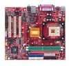
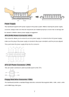
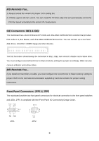
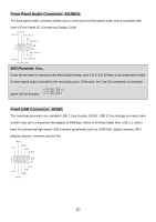
Chassis Intrusion Switch Connector: JCI1 (Optional) This connector is connected to 2-pin connector chassis switch. If the Chassis is open, the switch will be short. The system will record this status. To clear the warning, you must enter the BIOS setting and clear the status. CI NTRU GN D CD-In Connector: CD_IN1 The connector is for CD-ROM audio connector. GND R L SPDIF-OUT Connector: JSPDIF1 (Optional) The connector is used to connect SPDIF interface for digital audio transmission. SPD IF VC C G ND Fan Power Connectors: CFAN1/SFAN1 The CFAN1 (processor fan) and SFAN1 (system fan) support system cooling fan with +12V. They support three-pin head connector. When connecting the wire to the connectors, always take note that the red wire is the positive and should be connected to the +12V, the black wire is Ground and should be connected to GND. If the mainboard has a System Hardware Monitor chipset on-board, you must use a specially designed fan with speed sensor to take advantage of the CPU fan control. +1 2V GN D SE NS OR 8
-
 1
1 -
2
-
3
-
4
-
5
-
6
-
 7
7 -
 8
8 -
 9
9 -
 10
10 -
 11
11 -
 12
12 -
 13
13 -
 14
14 -
 15
15 -
 16
16 -
 17
17 -
18
-
19
-
20
-
21
-
22
-
23
-
24
-
25
-
26
-
27
-
28
-
29
-
30
-
31
-
32
-
33
-
34
-
35
-
36
-
37
-
38
-
39
-
40
-
41
-
42
-
43
-
44
-
45
-
46
-
47
-
48
-
49
-
50
-
51
-
52
-
53
-
54
-
55
-
56
-
57
-
58
-
59
-
60
-
61
-
62
-
63
-
64
-
65
-
66
-
67
-
68
-
69
-
70
-
71
-
72
-
73
-
74
-
75
-
76
-
77
-
78
-
79
-
80
-
81
-
82
-
83
-
84
-
85
-
86
-
87
-
88
-
89
-
90
-
91
-
92
-
93
-
94
-
95
-
96
-
97
-
98
-
99
-
100
-
101
-
102
-
103
-
104
-
105
-
106
-
107
-
108
-
109
-
110
-
111
 |
 |