MSI P7NGM DIGITAL User Guide - Page 57
Auto Disable DRAM/PCI Frequency
 |
UPC - 816909049602
View all MSI P7NGM DIGITAL manuals
Add to My Manuals
Save this manual to your list of manuals |
Page 57 highlights
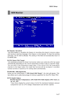
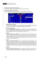
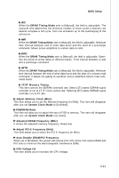
BIOS Setup tRC W hen the DRAM Timing M ode sets to [Manual], the field is adjustable. The rowcycle time determines the minimum number of clock cycles a memory row takesto complete a full cycle, from row activation up to the precharging of the ac t i ver ow . tWR When the DRAM Timing Mode sets to [Manual], the field is adjustable. Minimum time interval between end of write data burst and the start of a precharge command. Allows sense amplifiers to restore data to cells. tRRD W hen the DRAM Timing Mode sets to [Manual], the field is adjustable. Specifies the active-to-active delay of different banks. Time interval between a read and a precharge command. tWTR When the DRAM Timing Mode sets to [Manual], the field is adjustable. Minimum time interval between the end of write data burst and the start of a column-read command. It allows I/O gating to overdrive sense amplifiers before read command starts. 1T/2T Memory Timing This item controls the SDRAM command rate. Select [1T] makes SDRAM signal controller to run at 1T (T=clock cycles) rate. Selecting [2T] makes SDRAM signal controller run at 2T rate. Adjust Memory Clock (M Hz) This item allows you to set the Memory frequency (in MHz). This item will disappear after you set System Clock Mode to [Unlinked]. FSB/DRAM Ratio This item will allow you to adjust the ratio of FSB to memory. This item will disappear after you set System Clock Mode to [Linked]. Adjusted DRAM Frequency (MHz) It shows the adjusted memory frequency. Read-only. Adjust PCI-E Frequency (MHz) This field allows you to select the PCI-E frequency (in MHz). Auto Disable DRAM /PCI Frequency W hen set to [Enabled], the system will remove (turn off) clocks from empty DIMM and PCI slots to minimize the electromagnetic interference (EMI). CPU Voltage (V) This item allows you to increase the CPU voltage. 3-21
-
 1
1 -
2
-
3
-
4
-
5
-
6
-
7
-
8
-
9
-
10
-
11
-
12
-
13
-
14
-
15
-
16
-
17
-
18
-
19
-
20
-
21
-
22
-
23
-
24
-
25
-
26
-
27
-
28
-
29
-
30
-
31
-
32
-
33
-
34
-
35
-
36
-
37
-
38
-
39
-
40
-
41
-
42
-
43
-
44
-
45
-
46
-
47
-
48
-
49
-
50
-
51
-
 52
52 -
 53
53 -
 54
54 -
 55
55 -
 56
56 -
 57
57 -
 58
58 -
 59
59 -
 60
60 -
 61
61 -
 62
62 -
63
-
64
-
65
-
66
-
67
-
68
-
69
-
70
-
71
-
72
-
73
-
74
-
75
-
76
-
77
-
78
-
79
-
80
-
81
-
82
-
83
-
84
-
85
-
86
-
87
-
88
-
89
-
90
-
91
-
92
-
93
-
94
-
95
-
96
-
97
-
98
-
99
-
100
-
101
-
102
-
103
-
104
-
105
-
106
-
107
-
108
-
109
 |
 |