Mackie 1642-VLZ4 Spec Sheet - Page 8
Wood-Red Rd NE, Woodinville, WA, 98072 - vlz 4 sale
 |
View all Mackie 1642-VLZ4 manuals
Add to My Manuals
Save this manual to your list of manuals |
Page 8 highlights
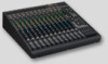
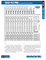
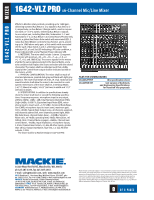
Effects to Monitor rotary controls, providing up to 15dB gain, delivering summed Aux Return 1 or 2 signals to Aux Send 1 or 2, respectively; an Aux Return 3 Assign switch, used in conjunction with a 1-2/3-4 switch, delivering Aux Return 3 signals to one output pair, including Main Mix, Submasters 1-2 and Submasters 3-4; an Aux Return 4 to Control Room/Phones Only switch; a global Aux Return Solo switch with associated LED; 2 rotary Aux Send Master controls for Aux Sends 1 and 2, providing up to 10dB above unity gain; a Solo switch with associated LED for each of Aux Sends 1 and 2; a blinking master Solo indicator LED, a Level Set LED indicating a PFL solo condition, a Power indicator LED; and a Phantom Power indicator LED. 6. METERING. The mixer shall include 1 stereo 12-segment LED meter with points at -30, -20, -10, -7, -4, -2, 0, +2, +4, +7, +10, and 28dB (Clip). The source signals for the meters shall be the same signals selected in the Source Matrix, and a solo condition shall replace the Source selection with the soloed channel(s). The meters shall be calibrated such that a 0dBu signal at the Control Room output shall be indicated as 0dB on the meters, ±1LED. 7. PHYSICAL CONFIGURATION. The mixer shall be made of steel and aluminum, painted dark gray and black with light gray graphics. The mixer shall weigh 18.2 lbs, (9.1 kg). Optional rackmount brackets shall allow the mixer to be mounted in a rack system. Dimensions of the mixer shall be, in Desktop Mode, 5.45" (138mm) in height, 16.63" (442mm) in width and 17.9" (455mm) in depth. 8. SPECIFICATIONS. In addition to specifications already cited, the mixer shall meet or exceed the following specifications. Frequency response, microphone input to any output, 20Hz to 60kHz, +0dB/-1dB; Total Harmonic Distortion (THD), 1k@+14dBu, 0.0007%; Equivalent Input Noise (EIN), microphone input to insert send, -129.5dBm; Common Mode Rejection (CMR), microphone input to insert send, maximum gain, 1kHz, ≥90dB; Typical Main Output noise, all channels assigned, odd channels panned left, even channels panned right, Main Mix fader down, channel faders down, -100dBu; Signal to Noise ratio, ref +4dBu operating level, 90dB; Attenuation, ref. 0dB @ 1kHz, Channel Mute engaged, -84dBu, Channel Gain control down, -84dBu; Input impedance, microphone inputs, 1.3 kΩ; Channel Insert return, 2.5 kΩ; All other inputs, greater than 10 kΩ; Output impedance, Tape Out, 1.1 kΩ; All other outputs, 120Ω. The mixer shall be a Mackie Designs 1642-VLZ PRO. FILES FOR DOWNLOADING 1642VLZP.PDF this specification sheet 1642VPAE.TXT text version of Architects and Engineering Specifications for insertion into proposals 16220 Wood-Red Rd NE, Woodinville, WA, 98072 ph 425.487.4333, fax 425.487.4337, e-mail: [email protected], web: www.mackie.com UK 2 Blenhiem Ct., Hurricane Way, Wickford, Essex, SS11 8YT, ph + 44 1268 571212, fax + 44 1268 570809, e-mail: [email protected] FRANCE Rue de la Guerlande, 71880 Chatenoy-le-Royal, ph 03.85.46.91.60, fax 03.85.46.91.60, e-mail: rcf.commercial @wanadoo.fr ITALY Via G. Ferraris 2/A, 42029 S. Maurizio (RE), ph +39.0522.354111, fax +39 0522 551875, e-mail: [email protected] GERMANY Kuhlmannstrasse 7, 48282 Emsdetten, ph +49.2572. 96042.0, fax +49.2572.96042.10, e-mail: [email protected] Mackie Designs continually engages in research related to product improvement. New material, production methods, and design refinements are introduced into existing products without notice as a routine expression of that philosophy. For this reason, any current Mackie Industrial product may differ in some respect from its published description, but will always equal or exceed the original design specifications unless otherwise stated. ©1999-2000 Mackie Designs Inc. All rights Reserved. The "Mackie." logo and the "Running Man" figure are registered trademarks of Mackie Designs Inc. VLZ, VLZ PRO and XDR are trademarks of Mackie Designs Inc. Part No. 091-297-00. 8
-
 1
1 -
2
-
 3
3 -
 4
4 -
 5
5 -
 6
6 -
 7
7 -
 8
8
 |
 |