Mackie M1200 Owner's Manual - Page 17
Balanced XLR Connectors, Balanced, TRS Plugs, Unbalanced 1/4 TS plug
 |
View all Mackie M1200 manuals
Add to My Manuals
Save this manual to your list of manuals |
Page 17 highlights
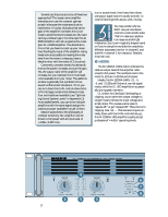
When connecting a balanced signal using the XLR or 1/4" jacks, they're wired thusly, per AES (Audio Engineering Society) standards: Hot (+) Cold (-) Shield (Ground) XLR Pin 2 Pin 3 Pin 1 TRS Tip Ring Shield Unbalanced TS (tip-sleeve) lines can be accommodated via the TRS jack. Make sure the cord terminates with a TS plug (like a guitar plug), or if it's a TRS plug (like a headphone plug), make sure the ring is tied to the shield, preferably at the source. SLEEVE SLEEVE TIP SHIELD 2 HOT COLD 3 1 SHIELD 1 Balanced XLR Connectors COLD 3 2 HOT 1 3 2 SHIELD COLD HOT RING SLEEVE SLEEVE RING TIP TIP Balanced 1⁄4" TRS Plugs RING (COLD) TIP (HOT) SLEEVE (SHIELD) TIP Unbalanced 1/4" TS plug RING (COLD) TIP (HOT) SLEEVE (SHIELD) You can connect an unbalanced XLR cable to the M•1200/M•1400, although this would be unusual - as unusual as an unbalanced XLR output. However, if you have an unbalanced XLR connection to make, refer to the "Connectors" section (Appendix C) at the back of this manual for more information. The M•1200/M•1400 amps expect to see a nominal signal level anywhere between the -10dBV "semipro" and +4 dBu "pro" standards, meaning almost any line-level mixer or other device can be plugged into the amp's INPUTs. Use the GAIN controls to adjust the gain of the amplifier to match the signal level you're using. If you set the AMP MODE switch in MONO or BRIDGE, use the CHANNEL 1 inputs only - the CHANNEL 2 inputs are disabled in this case. 1 CHANNEL / BRIDGE / MONO LOW CUT INPUT FILTER TYPICAL 35 Hz BALANCED OR UNBALANCED STAGE MONITOR 100 Hz OFF 170 Hz CONSTANT DIRECTIVITY HORN EQ /AIR EQ 4.5 kHz ON 2k Hz 5.6k Hz AIR EQQ OFF TYPICAL THRU AMP MODE STEREO TYPICAL MONO BRIDGE OUTPUT APPLICATION FULL RANGE LIMITER (CH1 & CH2) STEREO TYPICAL SUB WOOFER FREQUENCY 125Hz ON OFF 63Hz INPUT BALANCED OR UNBALANCED 2 CHANNEL LOW CUT FILTER TYPICAL 35 Hz STAGE MONITOR 100 Hz OFF 170 Hz CONSTANT DIRECTIVITY HORN EQ /AIR EQ ON 4.5k Hz THRU OFF TYPICAL 2k Hz 5.6k Hz AAIR EQ 17
-
 1
1 -
2
-
3
-
4
-
5
-
6
-
7
-
8
-
9
-
10
-
11
-
 12
12 -
 13
13 -
 14
14 -
 15
15 -
 16
16 -
 17
17 -
 18
18 -
 19
19 -
 20
20 -
 21
21 -
 22
22 -
23
-
24
-
25
-
26
-
27
-
28
-
29
-
30
-
31
-
32
-
33
-
34
-
35
-
36
-
37
-
38
-
39
-
40
-
41
-
42
-
43
 |
 |
