Mackie PPM608 Owner's Manual - Page 18
Gain Switch, Overload Ol Led, Channel Level
 |
View all Mackie PPM608 manuals
Add to My Manuals
Save this manual to your list of manuals |
Page 18 highlights
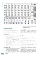
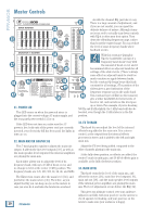
PPM608 21 22 23 24 25 26 27 28 29 30 30 26. OVERLOAD (OL) LED This LED will come on when the channel's input signal is too high. This should be avoided, as distortion will occur. If the LED is coming on regularly, check that the gain switch [28] is set correctly for your input and that the channel EQ [23-25] is not set with too much boost. 27. CHANNEL LEVEL This adjusts the level of each channel onto the main mix. The "U" mark indicates unity gain, meaning no increase or decrease of signal level. All the way up provides an additional 20 dB, should you need to boost a section of the band. If you find that the overall level is too quiet or too loud with the level near unity, you'll want to confirm the gain switch is set correctly. 28. GAIN SWITCH Engage this switch [low] on channels that have "louder" instrumentation connected. For example, loud singing or yelling or other loud-voiced instruments, such as bass, guitar or horns (whether connected via DI or mic'd). Disengage this switch [high] on channels that have "quieter" instrumentation connected. For example, spoken word shows, poetry readings, stand-up comedy or other quieter-voiced instruments such as fingerpicked acoustic guitar, cello, djembe, bouzouki and cats. Switch position MIC (XLR) Inputs IN (LOW) Gain = 25 dB OUT (HIGH) Gain = 45 dB LINE (TRS) Inputs Gain = 0 dB Gain = 20 dB 18 PPM608 Note that the gain switch has no effect on the line-level inputs and RCA inputs of channels 7 or 8. This is the first control that the input signals meet. It allows you to choose the level depending on the type of input source you have connected. If it is set incorrectly, then the input signals may overload the mixer, causing distortion, or it may come in too low, and be lost in noise. The gain switch allows you to make the initial level adjustment, appropriate for the connected device (mic or line). The channel level controls [27] are more for fine-tuning, to balance the channels appropriately for the song.
-
 1
1 -
2
-
3
-
4
-
5
-
6
-
7
-
8
-
9
-
10
-
11
-
12
-
 13
13 -
 14
14 -
 15
15 -
 16
16 -
 17
17 -
 18
18 -
 19
19 -
 20
20 -
 21
21 -
 22
22 -
 23
23 -
24
-
25
-
26
-
27
-
28
-
29
-
30
-
31
-
32
 |
 |
