Mackie ProFX8v2 Owners Manual - Page 8
ProFXv2 Front, Panel Features - mixer with usb and effects
 |
View all Mackie ProFX8v2 manuals
Add to My Manuals
Save this manual to your list of manuals |
Page 8 highlights
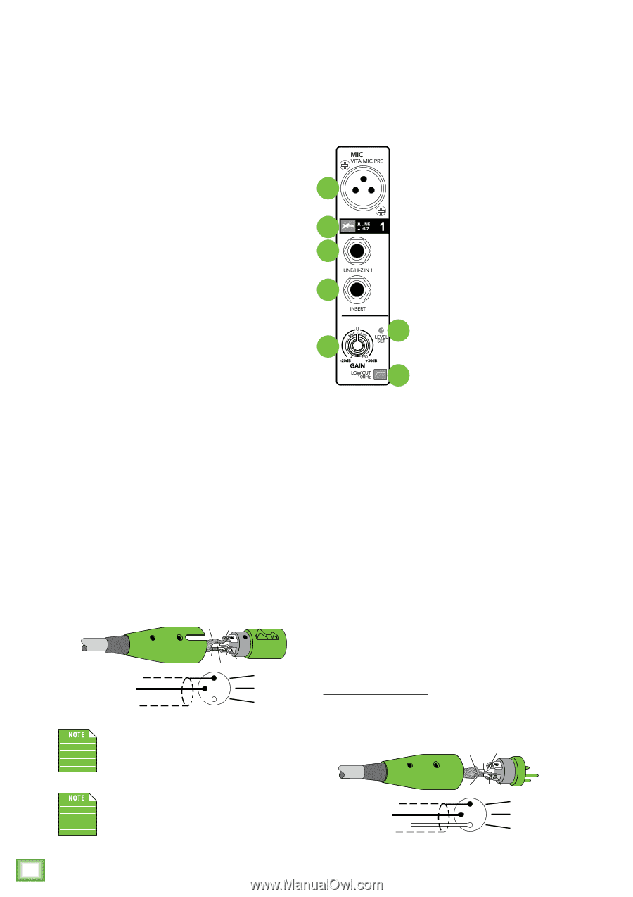
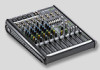
ProFX8v2 • ProFX12v2 • ProFX16v2 • ProFX22v2 • ProFX30v2 USB output FROM the mixer - recording, etc: In the USB out section [ProFX16v2, ProFX22v2, ProFX30v2] you may select either the main mix (disengaged) or subgroups 1-2 (engaged) from the conveniently titled USB out switch. The USB tap points for the subgroups are pre-fader and signals will show up on the DAW dependent upon how they are panned on the channels. In other words, if subgroups 1 and 2 are used to submix drums and those drums have a stereo image (e.g. overheads and toms channels are panned according to desire), this stereo image is retained in the DAW inputs. Any adjustments made to the subgroup drum levels during the show only pertain to the live show itself; recording levels are not adjusted in the DAW unless they are adjusted on the channels. Likewise, it is possible to record the main mix to take home a copy of the live show. These levels are also pre-main fader. Therefore, levels may be mixed up or down in the DAW later depending on the needs of the recording versus the live show. The end result is that fade-ins and/or fade-outs made during the show do not affect recorded levels. 4. Main L/R XLR Outputs The male XLR connectors provide a balanced line-level signal that represents the end of the mixer chain, where the fully mixed stereo signal enters the real world. Connect these to the left and right inputs of your main power amplifiers, powered speakers, or serial effects processor (like a graphic equalizer or compressor/limiter). They are wired as follows, according to standards specified by the AES (Audio Engineering Society): XLR Balanced Wiring: Pin 1 = Shield (ground) Pin 2 = Positive (+ or hot) Pin 3 = Negative (- or cold) SHIELD 1 ProFXv2 Front Panel Features Connections and Channel Strip The vertical channel strips look very similar, and have only a few differences 5 between them. Each channel works independently, and just controls the signals plugged into the inputs directly 6 above them. 7 5. Mic Inputs ProFXv2 mixers use 3-pin female 9 XLR connectors on all microphone inputs, with pin 1 wired to the grounded (earthed) shield, 10 11 pin 2 wired to the high (hot or positive polarity) side of the audio signal and pin 3 wired 12 to the low (cold or negative polarity) side of the signal. ProFX8v2 These female XLR connectors ProFX12v2 accept balanced mics or line level inputs from almost any type of source. The Vita mic preamps feature higher fidelity and headroom rivaling any standalone mic preamp on the market today. We use phantom-powered, balanced inputs just like the big mega-consoles, for exactly the same reason: This kind of circuit isexcellent at rejecting hum and noise. Professional ribbon, dynamic, and condenser mics all sound excellent through these inputs. The mic/line inputs will handle any kind of level you can toss at them, without overloading. Microphone-level signals are passed through the mixer's splendid microphone preamplifiers to become line-level signals. COLD 3 2 HOT 1 3 2 SHIELD COLD HOT The main L/R XLR outputs are located on the rear panel of the ProFX8v2 and ProFX12v2 and on the front panel of the ProFX16v2, ProFX22v2, and ProFX30v2. The XLR outputs are 6 dB hotter than the TRS outputs. They are wired as follows, according to standards specified by the AES (Audio Engineering Society). XLR Balanced Wiring: Pin 1 = Shield (ground) Pin 2 = Positive (+ or hot) Pin 3 = Negative (- or cold) SHIELD 2 HOT COLD 3 1 1 3 2 SHIELD COLD HOT 8 ProFX8v2 • ProFX12v2 • ProFX16v2 • ProFX22v2 • ProFX30v2
-
 1
1 -
2
-
 3
3 -
 4
4 -
 5
5 -
 6
6 -
 7
7 -
 8
8 -
 9
9 -
 10
10 -
 11
11 -
 12
12 -
 13
13 -
14
-
15
-
16
-
17
-
18
-
19
-
20
-
21
-
22
-
23
-
24
-
25
-
26
-
27
-
28
-
29
-
30
-
31
-
32
-
33
-
34
-
35
-
36
-
37
-
38
-
39
-
40
 |
 |