Mackie Serial9 Installation Guide - Page 4
Making the Connections, Specifications
 |
View all Mackie Serial9 manuals
Add to My Manuals
Save this manual to your list of manuals |
Page 4 highlights
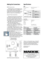
Making the Connections Specifications MIDI Connection The MIDI connection on the Serial•9 card is the same as the MIDI connection on the MIDI card it is replacing. Simply connect the supplied MIDI breakout cable to the bottom 9-pin connector on the Serial•9 card, and connect the 5-pin MIDI IN and MIDI OUT connectors to your MIDI interface. Serial 9-Pin Connection The Serial 9-Pin connection on the Serial•9 card is an RS-422 port that supports the Sony® 9-Pin device protocol. Connect the upper 9-pin connector to any industry standard Sony 9-Pin controller or device using a DB9 male to DB9 male serial computer cable (available at most computer supply outlets). Note: Make sure your Sony 9-Pin controller or device accepts a male DB9 connector. The Serial•9 card is shipped configured to operate as a device (DEV); that is, to connect to a controller and be controlled. This is indicated by the green LED on the Serial•9 card. It is possible to configure the Serial•9 to be the controller (CONT), to control another device. Simply move the five jumpers (JP1-JP5) on the Serial•9 card as shown in the illustration below to configure the card as a controller. This is indicated by the red LED on the Serial •9 card. Note: HDR24/96 software version 1.3 supports only device (DEV) protocol for the Serial•9. Please refer to the Software Release Notes, which can be found on Mackie website's HDR24/96 software downloads page, for complete information on the support of Serial•9 for all software versions. MIDI Electrical Interface: MIDI 1.0 Specification Data Rate: 31.25 kb/sec Pinout: 61 95 MIDI 5 2 4 3 1 OUT MIDI 5 2 4 3 1 IN MIDI Breakout Cable MIDI 9-Pin 1 2 3 4 5 6 7 8 9 Shell Function MIDI OUT Pin 4 MIDI IN Pin 4 MIDI OUT Pin 5 MIDI IN Pin 5 MIDI OUT Pin 2 Serial 9-Pin Electrical Interface: Data Rate: Parity: Data Bits: Stop Bits: EIA RS-422-A 38.4 kb/sec Odd 8 1 Indicators: Green LED (Device) Red LED (Controller) Pinout: Serial 9-Pin 1 2 3 4 5 6 7 8 9 Device Function Frame Ground Transmit A (-) Receive B (+) Receive Common N/C Transmit Common Transmit B (+) Receive A (-) Frame Ground Controller Function Frame Ground Receive A (-) Transmit B (+) Transmit Common N/C Receive Common Receive B (+) Transmit A (-) Frame Ground DEVICE/CONTROLLER CONFIGURATION JUMPERS IRQ IRQ2/9 IRQ3 IRQ4 IRQ5 IRQ7 IRQ10 IRQ11 IRQ12 IRQ15 I/O BASE ADDRESS BASE4 BASE5 BASE6 BASE8 J2 JP2 DEVICE JP3 JP4 JP5 JP1 DEVICE CONTROLLER J1 SERIAL•9 "Mackie," the "Running Man" figure, and "Serial•9" are trademarks or registered trademarks of Mackie Designs Inc. All other brand names mentioned are trademarks or registered trademarks of their respective holders, and are hereby acknowledged. © 2002 Mackie Designs Inc. All Rights Reserved. Printed in the U.S.A. MIDI DEVICE CONFIGURATION JP2 CONTROLLER CONFIGURATION JP2 DEVICE JP3 JP4 JP5 JP1 CONTROLLER DEVICE JP3 JP4 JP5 JP1 CONTROLLER Serial•9 Device/Controller Configuration 16220 Wood-Red Rd. NE • Woodinville, WA 98072 • USA US & Canada: 800/898-3211 Europe, Asia, Central & South America: 425/487-4333 Middle East & Africa: 31-20-654-4000 Fax: 425/487-4337 • www.mackie.com E-mail: [email protected]
-
 1
1 -
 2
2 -
 3
3 -
 4
4
 |
 |
