Magnavox MG-ANT-104 / Owners manual - Page 1
Magnavox MG-ANT-104 Manual
 |
View all Magnavox MG-ANT-104 manuals
Add to My Manuals
Save this manual to your list of manuals |
Page 1 highlights
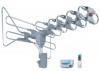
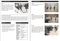
For the Installer (1 of 3) This antenna should be installed by a qualified professional. Refer to the diagrams shown below for installa tion. • Do not overtighten screws during installation. • For best signal reception, install the antenna as high as possible with a clear line of sight all around. Barriers around the anten na will decrease performance. • The motor, gears, and low-noise micro wave amplifier within the antenna are not designed to be serviced by the user. Repairs should be performed by a qualified service technician. DO NOT DISASSEMBLE. Step 1 Unfold and lock the dipoles of the VHF mast into place. Move the smaller "U" dipole to the other end of the boom. The motorized base should be fixed to a rooftop pole with the built-in wingnuts. Step2 Set the VHF mast on the base, taking care to match the peg on the base to the notch on the boom. The "U" dipole should be set to the right. Use two wing nuts and two 4x25mm screws to fix the mast to the motor ized base. DO NOT OVERTIGHTEN. Model No: MAG-ANT-104 360° Rotating Outdoor Antenna HD/DTV /UHF /VHF /FM Thank You Thank you for your purchase of the MAGNAVOX MAG-ANT-104 outdoor antenna. This manual is designed to help you learn how to assemble, operate and enjoy your new antenna for years to come. Please read this manual carefully and retain it for future reference. Installation This antenna is intended for outdoor use and should be installed on a roof or exterior of a building. Installation should be done by a qualified professional who can evaluate the installation site to safely secure the antenna and find a location that will maximize reception from local broadcast stations. Overview After the antenna has been securely installed outside: 1. Use the included 50' coaxial cable to connect the antenna to the ANTENNA INPUT of the control box. 2. Connect the TV1 cable of the control box to an available TV INPUT. {Con nect a second TV to TV2.) 3. Connect the control box to AC household power. Once all connec tions have been made, you can turn everything on. 4. Set the input mode of the TV to match the connector used with the antenna (e.g., TV ANT). The names of these connectors and modes differ by manufacturer. 5. Use the TV system menu to scan for available channels. Refer to the instructions provided by the TV manufacturer to learn more. r � Images in the figure may not match the actual product. The figure is for illustra tive purposes, only. � ) 50' coaxial cable (included) Television Remote control
-
 1
1 -
 2
2
 |
 |