Makita 5007MG Owners Manual - Page 7
Bevel cutting, Sighting, Switch action, Electric brake, Lighting the lamp - model
 |
View all Makita 5007MG manuals
Add to My Manuals
Save this manual to your list of manuals |
Page 7 highlights
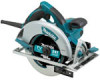
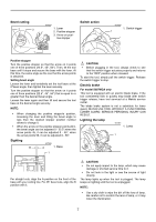
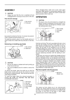
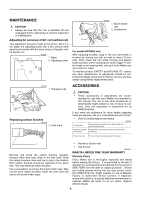
Bevel cutting 2 3 22.5 45 56 007327 1. Lever 2. Positive stopper 3. Arrow on posi- tive stopper Switch action 007329 1. Switch trigger 1 1 Positive stopper Turn the positive stopper so that the arrow on it points one of three positions (22.5°, 45°, 56°). Then, tilt the tool base until it stops and secure the base with the lever. At this time, the same angle as the one that the arrow points is obtained. Setting bevel angle Loosen the lever and tentatively set the tool base at the 0°bevel angle, then tighten the lever securely. Turn the positive stopper so that the arrow on it points one of three positions (22.5°, 45°, 56°) that is equal to or greater than the desired bevel angle. Loosen the lever again and then tilt and secure the tool base at the desired angle securely. NOTE: • When changing the positive stopper's position, loosening the lever and tilting the bevel angle to less than the desired stopper position number allows to change it. • When the arrow on the positive stopper points 22.5, the bevel angle can be adjusted 0 - 22.5°;when the arrow points 45, it can be adjusted 0 - 45°; when the arrow points 56, it can be adjusted 0 - 56°. Sighting B 007328 A 1. Base 1 CAUTION: • Before plugging in the tool, always check to see that the switch trigger actuates properly and returns to the "OFF" position when released. To start the tool, simply pull the switch trigger. Release the switch trigger to stop. Electric brake For model 5007MGA only This tool is equipped with an electric blade brake. If the tool consistently fails to quickly stop blade after switch trigger release, have tool serviced at a Makita service center. The blade brake system is not a substitute for lower guard. NEVER USE TOOL WITHOUT A FUNCTIONING LOWER GUARD. SERIOUS PERSONAL INJURY CAN RESULT. Lighting the lamp 007351 1. Lamp 1 For straight cuts, align the A position on the front of the base with your cutting line. For 45° bevel cuts, align the B position with it. CAUTION: • Do not apply impact to the lamp, which may cause damage or shorted service time to it. • Do not look in the light or see the source of light directly. The lamp lights up when the tool is plugged. The lamp keeps on lighting until the tool is unplugged. NOTE: • Use a dry cloth to wipe the dirt off the lens of lamp. Be careful not to scratch the lens of lamp, or it may lower the illumination. 7
-
 1
1 -
 2
2 -
 3
3 -
 4
4 -
 5
5 -
 6
6 -
 7
7 -
 8
8 -
 9
9 -
 10
10 -
 11
11 -
 12
12 -
13
-
14
-
15
-
16
-
17
-
18
-
19
-
20
-
21
-
22
-
23
-
24
-
25
-
26
-
27
-
28
-
29
-
30
-
31
-
32
 |
 |
