Makita 9015A Owners Manual - Page 6
Functional, Description, Assembly
 |
View all Makita 9015A manuals
Add to My Manuals
Save this manual to your list of manuals |
Page 6 highlights
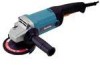
FUNCTIONAL DESCRIPTION CAUTION: • Always be sure that the tool is switched off and unplugged before adjusting or checking function on the tool. 1 1. Shaft lock 001025 Shaft lock CAUTION: • Never actuate the shaft lock when the spindle is moving. The tool may be damaged. Press the shaft lock to prevent spindle rotation when installing or removing accessories. 1. Switch trigger 001039 Switch action CAUTION: • Before plugging in the tool, always check to see that the switch trigger actuates properly and returns to the "OFF" 1 position when released. To start the tool, simply pull the switch trigger. Release the switch trigger to stop. ASSEMBLY CAUTION: • Always be sure that the tool is switched off and unplugged before carrying out any work on the tool. 001056 Installing side grip (handle) CAUTION: • Always be sure that the side grip is installed securely before operation. Screw the side grip securely on the position of the tool as shown in the figure. 6
-
 1
1 -
 2
2 -
 3
3 -
 4
4 -
 5
5 -
 6
6 -
 7
7 -
 8
8 -
 9
9 -
 10
10 -
 11
11 -
 12
12 -
13
-
14
-
15
-
16
 |
 |
