Makita 9557PB Owners Manual - Page 5
Assembly - brushes
 |
View all Makita 9557PB manuals
Add to My Manuals
Save this manual to your list of manuals |
Page 5 highlights
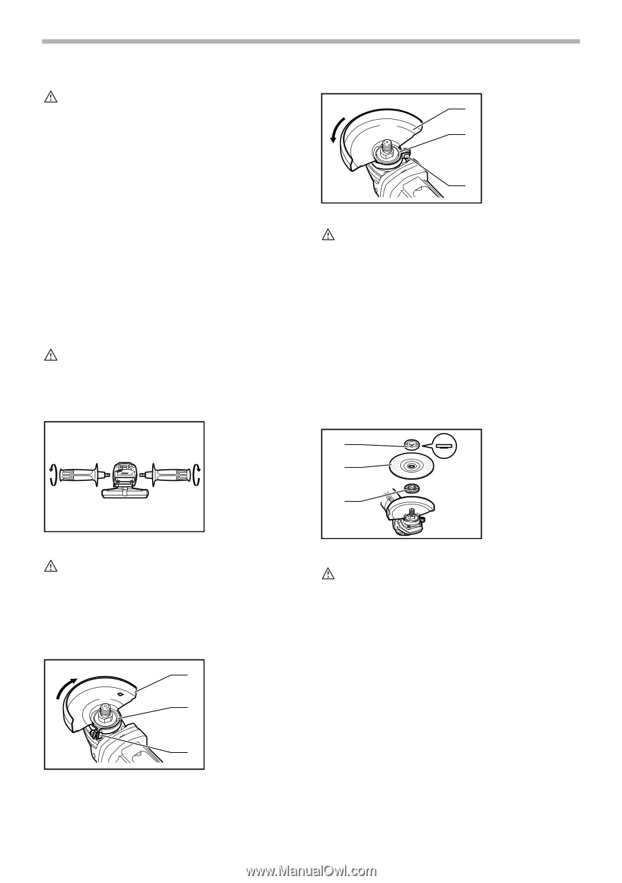
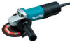
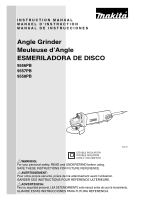
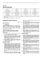
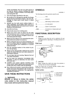
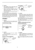
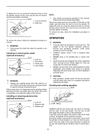
CAUTION: • Before plugging in the tool, always check to see that the switch lever actuates properly and returns to the "OFF" position when released. • Switch can be locked in "ON" position for ease of operator comfort during extended use. Apply caution when locking tool in "ON" position and maintain firm grasp on tool. • Do not pull the switch lever forcibly without pushing in the lock-off lever. To prevent the switch lever from accidentally pulled, a lock-off lever is provided. To start the tool, pull the lock-off lever toward the operator and then pull the switch trigger. Release the switch lever to stop. For continuous operation, pull the switch lever and then push in the lock button. To stop the tool from the locked position, pull the switch lever fully, then release it. ASSEMBLY CAUTION: • Always be sure that the tool is switched off and unplugged before carrying out any work on the tool. Installing side grip (handle) 006113 9557PB/9558PB 006115 1. Wheel guard 1 2. Bearing box 3. Screw 2 3 CAUTION: • When using a depressed center grinding wheel/ Multi-disc, flex wheel, wire wheel brush or cut-off wheel, the wheel guard must be fitted on the tool so that the closed side of the guard always points toward the operator. Mount the wheel guard with the protrusion on the wheel guard band aligned with the notch on the bearing box. Then rotate the wheel guard around 180 degrees. Be sure to tighten the screw securely. To remove wheel guard, follow the installation procedure in reverse. Installing or removing depressed center grinding wheel/Multi-disc 006116 1 1. Lock nut 2. Depressed cen- 2 ter wheel/Multidisc 3. Inner flange 3 CAUTION: • Always be sure that the side grip is installed securely before operation. Screw the side grip securely on the position of the tool as shown in the figure. Installing or removing wheel guard 006114 9556PB 1. Wheel guard 1 2. Bearing box 3. Screw 2 WARNING: • Always use supplied guard when depressed center grinding wheel/Multi-disc is on tool. Wheel can shatter during use and guard helps to reduce chances of personal injury. Mount the inner flange onto the spindle. Fit the wheel/ disc on the inner flange and screw the lock nut onto the spindle. 3 5
-
 1
1 -
 2
2 -
 3
3 -
 4
4 -
 5
5 -
 6
6 -
 7
7 -
 8
8 -
 9
9 -
 10
10 -
 11
11 -
12
-
13
-
14
-
15
-
16
-
17
-
18
-
19
-
20
-
21
-
22
-
23
-
24
-
25
-
26
-
27
-
28
 |
 |