Makita AC001 Makita AC001 Instruction Manual - Page 9
Installation And, Break-in, Procedures
 |
View all Makita AC001 manuals
Add to My Manuals
Save this manual to your list of manuals |
Page 9 highlights
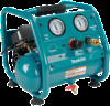
reaches "cut-out" pressure. PRESSURE SWITCH: The pressure switch automatically starts the motor when the air tank pressure drops to the factory set "cut-in" pressure. It stops the motor when the air tank pressure reaches the factory set "cut-out" pressure. SAFETY VALVE: If the pressure switch does not shut off the air compressor at its "cut-out" pressure setting, the safety valve will protect against high pressure by "popping out" at its factory set pressure (slightly higher than the pressure switch "cut-out" setting). OUTLET PRESSURE GAUGE: The outlet pressure gauge indicates the air pressure available at the outlet side of the regulator. This pressure is controlled by the regulator and is always less or equal to the tank pressure. See "Operating Procedures". TANK PRESSURE GAUGE: The tank pressure gauge indicates the air pressure in the tank. REGULATOR: The air pressure coming from the air tank is controlled by the regulator knob. Turn the knob clockwise to increase pressure and counterclockwise to decrease pressure. To avoid minor re-adjustment after making a change in pressure setting, always approach the desired pressure from a lower pressure. When reducing from a higher to a lower setting, first reduce to some pressure less than desired pressure. Depending on the air requirements of each particular accessory, the outlet regulated air pressure may have to be adjusted while you are operating the accessory. INSTALLATION AND BREAK-IN PROCEDURES LOCATION OF THE AIR COMPRESSOR Locate the air compressor in a clean, dry and well-ventilated area. The air must be kept clear of obstructions, which could reduce air delivery of the air compressor. The air compressor should be located at least 12 inches away from the wall or other obstructions that will interfere with the flow of air. The air compressor head and shroud are designed to allow for proper cooling. If humidity is high, an air filter can be installed on the air outlet adapter to remove excessive moisture. Page 9
-
 1
1 -
2
-
3
-
 4
4 -
 5
5 -
 6
6 -
 7
7 -
 8
8 -
 9
9 -
 10
10 -
 11
11 -
 12
12 -
 13
13 -
 14
14 -
15
-
16
-
17
-
18
-
19
-
20
-
21
-
22
-
23
-
24
-
25
-
26
-
27
-
28
-
29
-
30
-
31
-
32
-
33
-
34
-
35
-
36
-
37
-
38
-
39
-
40
 |
 |
