Makita BHP454 Owners Manual - Page 6
Assembly - chuck
 |
View all Makita BHP454 manuals
Add to My Manuals
Save this manual to your list of manuals |
Page 6 highlights
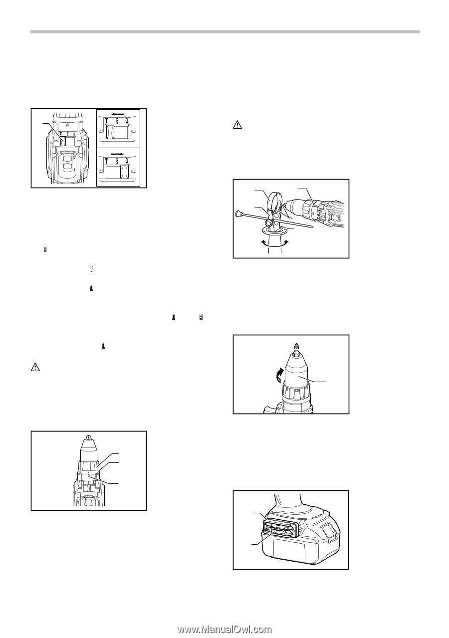
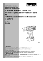
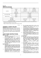
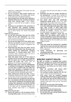
damaged. • Do not use the speed change lever while the tool is running. The tool may be damaged. Selecting the action mode 1. Action mode 1 change lever 009002 This tool employs an action mode change lever. Select one of the three modes suitable for your work needs by using this lever. For rotation only, slide the lever so that it points toward the mark on the tool body. For rotation with hammering, slide the lever so that it points toward the mark on the tool body. For rotation with clutch, slide the lever so that the it points toward the mark on the tool body. NOTE: • When changing the position from " " to " ", it may be a little difficult to slide the mode change lever. At this time, switch on and run the tool for a second at the " " position, then stop the tool and slide to your desired position. CAUTION: • Always set the lever correctly to your desired mode mark. If you operate the tool with the lever positioned halfway between the mode marks, the tool may be damaged. Adjusting the fastening torque 1. Adjusting ring 2. Graduations 1 3. Arrow 2 3 009003 Before actual operation, drive a trial screw into your material or a piece of duplicate material to determine which torque level is required for a particular application. ASSEMBLY CAUTION: • Always be sure that the tool is switched off and the battery cartridge is removed before carrying out any work on the tool. Installing side grip (auxiliary handle) 1 5 2 4 3 1. Steel band 2. Grip base 3. Side grip 4. Protrusion 5. Groove 009004 Always use the side grip to ensure operating safety. Insert the side grip so that the protrusions on the grip base and steel band fit in between the grooves on the tool barrel. Then tighten the grip by turning clockwise. Installing or removing driver bit or drill bit 1. Sleeve 1 009005 Turn the sleeve counterclockwise to open the chuck jaws. Place the bit in the chuck as far as it will go. Turn the sleeve clockwise to tighten the chuck. To remove the bit, turn the sleeve counterclockwise. Installing bit holder 1. Bit holder 2. Bit 1 The fastening torque can be adjusted in 16 steps by turning the adjusting ring so that its graduations are aligned with the arrow on the tool body. The fastening torque is minimum when the number 1 is aligned with the arrow, and maximum when the number 16 is aligned with the arrow. 2 006725 6
-
 1
1 -
 2
2 -
 3
3 -
 4
4 -
 5
5 -
 6
6 -
 7
7 -
 8
8 -
 9
9 -
 10
10 -
 11
11 -
 12
12 -
13
-
14
-
15
-
16
-
17
-
18
-
19
-
20
-
21
-
22
-
23
-
24
-
25
-
26
-
27
-
28
-
29
-
30
-
31
-
32
 |
 |