Makita CT322W XFD01 Instruction Manual - Page 6
Assembly
 |
View all Makita CT322W manuals
Add to My Manuals
Save this manual to your list of manuals |
Page 6 highlights
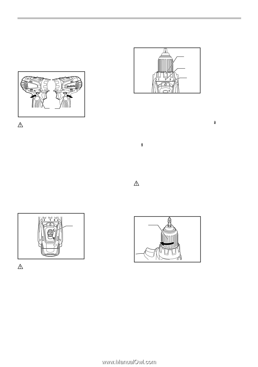
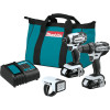
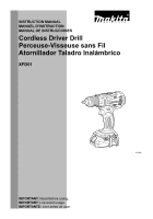
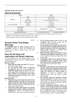
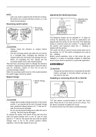
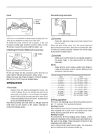
NOTE: • Use a dry cloth to wipe the dirt off the lens of lamp. Be careful not to scratch the lens of lamp, or it may lower the illumination. Reversing switch action 1. Reversing switch lever Adjusting the fastening torque 1. Adjusting ring 1 2. Graduation 3. Pointer 2 3 A B 1 011363 CAUTION: • Always check the direction of rotation before operation. • Use the reversing switch only after the tool comes to a complete stop. Changing the direction of rotation before the tool stops may damage the tool. • When not operating the tool, always set the reversing switch lever to the neutral position. This tool has a reversing switch to change the direction of rotation. Depress the reversing switch lever from the A side for clockwise rotation or from the B side for counterclockwise rotation. When the reversing switch lever is in the neutral position, the switch trigger cannot be pulled. Speed change 1. Speed change lever 1 011365 The fastening torque can be adjusted in 17 steps by turning the adjusting ring so that its graduations are aligned with the pointer on the tool body. The fastening torque is minimum when the number 1 is aligned with the pointer, and maximum when the marking is aligned with the pointer. The clutch will slip at various torque levels when set at the number 1 to 16. The clutch is designed not to slip at the marking. Before actual operation, drive a trial screw into your material or a piece of duplicate material to determine which torque level is required for a particular application. ASSEMBLY CAUTION: • Always be sure that the tool is switched off and the battery cartridge is removed before carrying out any work on the tool. Installing or removing driver bit or drill bit 1. Sleeve 1 011364 CAUTION: • Always set the speed change lever fully to the correct position. If you operate the tool with the speed change lever positioned halfway between the "1" side and "2" side, the tool may be damaged. • Do not use the speed change lever while the tool is running. The tool may be damaged. To change the speed, first switch off the tool and then slide the speed change lever to the "2" side for high speed or "1" side for low speed. Be sure that the speed change lever is set to the correct position before operation. Use the right speed for your job. 011366 Turn the sleeve counterclockwise to open the chuck jaws. Place the bit in the chuck as far as it will go. Turn the sleeve clockwise to tighten the chuck. To remove the bit, turn the sleeve counterclockwise. 6
-
 1
1 -
 2
2 -
 3
3 -
 4
4 -
 5
5 -
 6
6 -
 7
7 -
 8
8 -
 9
9 -
 10
10 -
 11
11 -
 12
12 -
13
-
14
-
15
-
16
-
17
-
18
-
19
-
20
-
21
-
22
-
23
-
24
-
25
-
26
-
27
-
28
 |
 |