Makita GA4542C GA4542C/GA5042C Instruction Manual - Page 8
Assembly
 |
View all Makita GA4542C manuals
Add to My Manuals
Save this manual to your list of manuals |
Page 8 highlights
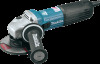
overheating. When the load returns to admissible levels, the tool will operate as normal. Mechanical brake For model GA4543C, GA5043C Mechanical brake is activated after the tool is switched off. The brake does not work when the power supply is shut down with the switch still on. ASSEMBLY CAUTION: • Always be sure that the tool is switched off and unplugged before carrying out any work on the tool. Installing side grip (handle) For tool with locking screw type wheel guard 1. Wheel guard 2. Bearing box 3. Screw 1 2 3 012733 Mount the wheel guard with the protrusions on the wheel guard band aligned with the notches on the bearing box. Then rotate the wheel guard around 180 ゚ counterclockwise. Be sure to tighten the screw securely. To remove wheel guard, follow the installation procedure in reverse. For tool with clamp lever type wheel guard 012724 CAUTION: • Always be sure that the side grip is installed securely before operation. Screw the side grip securely on the position of the tool as shown in the figure. Installing or removing wheel guard (For depressed center wheel, multi-disc, flex wheel, wire wheel brush / abrasive cut-off wheel, diamond wheel) 1 1. Wheel guard 2. Bearing box 3. Screw 4. Lever 2 3 4 009430 Pull the lever in the direction of the arrow after loosening the screw. Mount the wheel guard with the protrusions on the wheel guard band aligned with the notches on the bearing box. Then rotate the wheel guard around 180 ゚. 1 2 1. Screw 2. Lever WARNING: • When using a depressed center wheel, multi-disc, flex wheel or wire wheel brush, the wheel guard must be fitted on the tool so that the closed side of the guard always points toward the operator. • When using an abrasive cut-off / diamond wheel, be sure to use only the special wheel guard designed for use with cut-off wheels. 009431 Tighten the wheel guard with fastening the screw after pulling lever in the direction of the arrow. The setting angle of the wheel guard can be adjusted with the lever. To remove wheel guard, follow the installation procedure in reverse. Installing or removing depressed center wheel or multi-disc (optional accessory) WARNING: • When using a depressed center wheel or multi-disc, the wheel guard must be fitted on the tool so that the closed side of the guard always points toward the operator. 8
-
 1
1 -
2
-
 3
3 -
 4
4 -
 5
5 -
 6
6 -
 7
7 -
 8
8 -
 9
9 -
 10
10 -
 11
11 -
 12
12 -
 13
13 -
14
-
15
-
16
-
17
-
18
-
19
-
20
-
21
-
22
-
23
-
24
-
25
-
26
-
27
-
28
-
29
-
30
-
31
-
32
-
33
-
34
-
35
-
36
-
37
-
38
-
39
-
40
-
41
-
42
-
43
-
44
-
45
-
46
-
47
-
48
 |
 |
