Makita HP2050 Technical Reference
Makita HP2050 Manual
 |
View all Makita HP2050 manuals
Add to My Manuals
Save this manual to your list of manuals |
Makita HP2050 manual content summary:
- Makita HP2050 | Technical Reference - Page 1
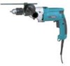
TECHNICAL INFORMATION Models No. HP2050, HP2050F, HP2051, HP2051F Description 2 Speed Hammer Drills 20mm CONCEPT AND MAIN APPLICATIONS PRODUCT P 1 / 17 L Makita new 700W class hammer drills with extra low vibration level, yet with superior working performance has just been H released. The - Makita HP2050 | Technical Reference - Page 2
HP2050F/ HP2051F Comparison of products Cord guard is not only tough but also very flexible to protect cable from disconnection. Model No. MAKITA Specifications HP2050 F type) No Vibration in hammer drill mode (blowing direction) : m/s2 * 6.0 7.0 Noise level in hammer drill mode : dB(A) - Makita HP2050 | Technical Reference - Page 3
with :ø 24 mm (15/16") bit MAKITA HP2050(F)/HP2051(F) Competitor A Model A-1 Competitor A Model A-2 120 100 120 * Working mode : Drill / Low Speed * When hammer drilling with ø 36mm (1-7/16") bit MAKITA HP2050(F)/HP2051(F) Competitor A Model A-1 Competitor A Model A-2 125 100 100 0 50 100 - Makita HP2050 | Technical Reference - Page 4
abrasion. See Fig. 1. Gear housing Spindle Cam Apply 25g of MAKITA grease N No.1 to the inner part of gear housing. Gear housing Spur gear 29-37 Fig. 1 Change lever B < 2 >Assembling and disassembling ( 1 ) Disassembling drill chuck See Fig. 2. 1. Hold the flat portion of spindle with No - Makita HP2050 | Technical Reference - Page 5
Repair ( 3) Disassembling gear section See Fig. 3. 1. Separate gear housing cover from gear housing. 2. Pull out lock plate. 3. Then change lever B, pin, rack 12 with change plate B - Makita HP2050 | Technical Reference - Page 6
Repair 4. Insert pin 4 through rack 12 into gear housing. And then, rush rack 12 until it reaches the bottom wall of gear housing. See Fig. 8. Keeping - Makita HP2050 | Technical Reference - Page 7
Repair P 7 / 17 ( 5) Disassembling bearing retainer 20-36 and oil seal 19 1. 1R292 Wrench for bearing retainer Loosening Fig. 11 ( 6) Assembling bearing retainer 20-36 and oil seal 19 1. Apply MAKITA grease N No.1 to oil seal, and assemble oil seal 19 pressing with arbor press. See Fig. 12. < - Makita HP2050 | Technical Reference - Page 8
Repair ( 7) Disassembling cam A 1. After removing bearing retainer 20-36 and oil seal 19, disassemble ring spring 11 from spindle. And disassemble spindle section by pulling out from the drill chuck side of gear housing as illustrated in Fig 14. Gear housing Ring spring 11 P 8 / 17 Spindle - Makita HP2050 | Technical Reference - Page 9
Repair P 9 / 17 2. Put the spindle on 1R035 "bearing setting plate" and assemble ball bearing 6202LLB and cam A to the spindle by pressing with arbor press as - Makita HP2050 | Technical Reference - Page 10
Circuit diagram HP2050F and HP2051F (equipped with flash light) For Europe, High voltage area Color index of lead wires Black White Red Orange Blue Transparent Insulated terminal Noise suppressor P 10 / 17 Insulated terminal Choke coil Field A Brush holder Field B Field A Brush holder Field B - Makita HP2050 | Technical Reference - Page 11
Circuit diagram HP2050 and HP2051 (without flash light) For Europe, High voltage area Color index of lead wires Black White Red Orange Blue Transparent Insulated terminal Noise suppressor P 11 / 17 Insulated terminal Choke coil Field A Brush holder Field B Field A Brush holder Field B 2 3 4 - Makita HP2050 | Technical Reference - Page 12
Circuit diagram HP2050 and HP2051 (without flash light) For Great Britain, low voltage Color index of lead wires Black White Red Orange Blue Transparent P 12 / 17 Choke coil Field A Brush holder Field B Field A Brush holder Field B 2 3 4 1 M1 M2 C1 1 C2 2 Connected to field core Noise - Makita HP2050 | Technical Reference - Page 13
Circuit diagram HP2050 and HP2051 (without flash light) For other countries Color index of lead wires Black White Red Orange Blue P 13 / 17 Field A Brush holder Field B Field A Brush holder Field B 2 3 4 1 M1 M2 C1 1 C2 2 Noise suppressor Power supply cord - Makita HP2050 | Technical Reference - Page 14
diagram P 14 / 17 HP2050F and HP2051F (equipped with flash light) For Europe, High voltage area The electrical parts marked with * have to wires with this lead holder. * Switch lead wire (blue) for connecting to brush holder * Field lead wire (white) for connecting to insulated terminal Fix with - Makita HP2050 | Technical Reference - Page 15
Wiring diagram P 15 / 17 HP2050 and HP2051 (without flash light) For Europe, High voltage area The electrical parts marked with * have to be wires with this lead holder. * Switch lead wire (blue) for connecting to brush holder * Field lead wire (white) for connecting to insulated terminal Fix with - Makita HP2050 | Technical Reference - Page 16
Wiring diagram HP2050 and HP2051 (without flash light) For Great Britain, low voltage Choke coil Set choke coil in the position illustrated. Fix field lead wire (black) for connecting to switch, with lead holder. Brush holder Fix the following lead wires with this lead holder. * Switch lead wire ( - Makita HP2050 | Technical Reference - Page 17
Wiring diagram HP2050 and HP2051 (without flash light) For other countries Fix field lead wire (black) for connecting to switch, with lead holder. Brush holder Fix the following lead wires with this lead holder. * Switch lead wire (red) for connecting to brush holder * Lead wire (black) connecting
-
 1
1 -
 2
2 -
 3
3 -
 4
4 -
 5
5 -
 6
6 -
 7
7 -
8
-
9
-
10
-
11
-
12
-
13
-
14
-
15
-
16
-
17
 |
 |

Continuous Rating (W)
Voltage (V)
Cycle (Hz)
Input
Output
Max. Output(W)
110
120
720
720
720
720
720
360
360
360
360
360
660
660
660
660
660
220
230
240
* Chuck key S-13 (only for HP2050 and hP2050F)
.................
1 pc.
* Key holder
(only for HP2050 and hP2050F)
........................
1 pc.
* Depth guide
............................................................................
1 pc.
* Side grip set
...........................................................................
1 pc.
* Plastic carrying case
...............................................................
1 pc.
6.9
6.6
3.4
3.3
3.2
Models No.
Description
PRODUCT
Current (A)
T
ECHNICAL INFORMATION
C
ONCEPT AND MAIN APPLICATIONS
S
pecification
S
tandard equipment
O
ptional accessories
< Note >
The standard equipment for the tool shown may differ from country to country.
P 1 / 17
HP2050, HP2050F, HP2051, HP2051F
Makita new 700W class hammer drills with extra low
vibration level, yet with superior working performance has just been
released.
The features and benefits are :
* Slim and smart shape hammer drills, yet loaded with torque limiter
* Extra-low vibration level for comfortable and less fatigue operation
* Model HP2050F and HP2051F are equipped
with built-in job light
* HP2051 and HP2051F are equipped with
keyless drill chucks.
2 Speed Hammer Drills 20mm
Dimensions : mm
( " )
Width ( W )
Height ( H )
Length ( L )
Model No.
360 (14-1/8)
220 (8-5/8)
70 (2-3/4)
L
H
W
50 / 60
50 / 60
50 / 60
50 / 60
50 / 60
Blows per min.
: (min
-1
= bpm)
Concrete
Model No.
HP2050.
0 - 2,900
0 - 58,000
0 - 24,000
0 - 1,200
HP2050F
HP2051
HP2051F.
Chuck ability : mm ( " )
Keyless chuck
Reverse switch
LED job light
No load speed
: (min
-1
= rpm)
Drilling capacity
: mm ( " )
Steel
Wood
Protection from electric shock
Net weight :Kg
(lbs )
Cord length : m ( ft )
(High)
(Low)
(High)
(Low)
(High)
(Low)
(High)
(Low)
(High)
(Low)
Yes
Yes
Yes
Yes
No
No
No
No
1.5 - 13.0 (1/16 - 1/2)
20 (3/4)
20 (3/4)
40 (1-9/16)
25 (1)
13 (1/2)
8 (5/16)
by double insulation
Yes
2.5 (8.2)
2.3 (5.1)
* TCT. drill bit 5 - 19mm
* Drill bit for metal 13mm
* Drill bit for wood 40mm
* Center drill bit for hole saw 16 - 90mm
* Metal borer 14 - 35mm
* Depth guide
* Wrench 9
* Blow-out bulb
* Keyless drill chuck
* Drill chuck set
* Side grip set
* Type 43 drill stand
* Chuck key S-13
(for HP2050, HP2050F)
372 (14-1/4)
HP2050(F)
HP2051(F)