Makita JS1602 Owners Manual - Page 5
Assembly - shear
 |
View all Makita JS1602 manuals
Add to My Manuals
Save this manual to your list of manuals |
Page 5 highlights
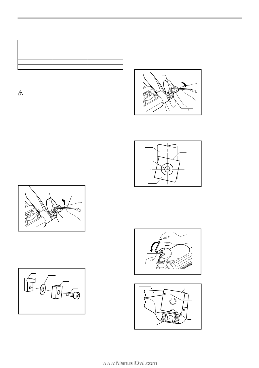
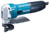
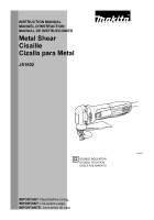
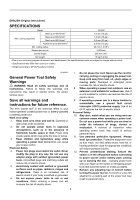
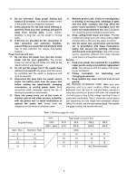
Material Mild steel (A) Hard steel (B) Stainless steel Aluminum plate 006425 Tensile Strength (N/mm2) 400 600 800 200 ASSEMBLY Max. cutting thickness (mm) 1.6 (16 ga) 1.2 (18 ga) 0.8 (22 ga) 2.5 (13 ga) CAUTION: • Always be sure that the tool is switched off and unplugged before carrying out any work on the tool. Blade inspection Before using the tool, check the blades for wear. Dull, worn blades will result in poor shearing action, and the service life of the tool will be shortened. Rotating or replacing blades Both the upper and lower blades have four cutting edges on each side (the front and back). When the cutting edge becomes dull, rotate both the upper and the lower blades 90° to expose new cutting edges. When all eight edges are dull on both the upper and lower blades, replace both blades with new ones. Each time blades are rotated or replaced, proceed as follows. 1. Hex wrench 3 2. Loosen 2 1 3. Upper blade securing bolt 4. Lower blade 5. Upper blade 4 5 013077 Remove the blade securing bolts with the hex wrench provided and then rotate or replace the blades. Some tools have one washer between the upper blade and the blade holder.When the tool has the washer, be sure to use the thin washer when reassembling. 1 2 1. Blade holder 2. Thin washer 3 3. Upper blade 4 4. Upper blade securing bolt 013078 NOTE: • No thin washers are used for the lower blade. Install the upper blade and tighten the upper blade securing bolt with the hex wrench. Press up on the upper blade while tightening it. 1 2 1. Upper blade securing bolt 2. Tighten 3. Upper blade 3 013079 After securing the upper blade, be sure that there is no gap left between the upper blade and the beveled surface of the blade holder. 1. Blade holder 1 2. Upper blade 4 securing bolt 2 3. Upper blade 4. No gap allowed 3 013080 When installing the lower blade onto the yoke, the lower blade should be pressed against the yoke so as to be contacting the beveled portions A and B of the yoke and the tip C of the lower blade positioning screw while you tighten the lower blade securing bolt. There must be no clearance between A, B and C during installation. 1 3 2 1. Tighten 2. Lower blade 3. Yoke 013081 1 2 013082 3 1. Yoke 2. Lower blade positioning A screw 3. Lower blade B C 5
-
 1
1 -
 2
2 -
 3
3 -
 4
4 -
 5
5 -
 6
6 -
 7
7 -
 8
8 -
 9
9 -
 10
10 -
 11
11 -
12
-
13
-
14
-
15
-
16
-
17
-
18
-
19
-
20
 |
 |