Makita XNJ01 XNJ01Z Instruction Manual - Page 6
Assembly
 |
View all Makita XNJ01 manuals
Add to My Manuals
Save this manual to your list of manuals |
Page 6 highlights
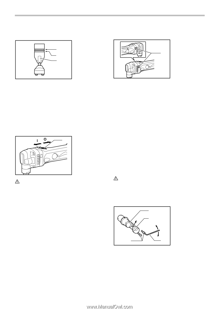
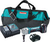
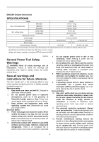
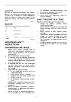
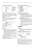
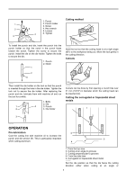
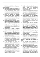
Permissible cutting thickness 1. Gauge for cutting stainless: 1 1.2 mm (3/64") 2 2. Gauge for 3 cutting mild steel: 1.6 mm (1/16") 3. Notch 004775 The thickness of material to be cut depends upon the tensile strength of the material itself. The groove on the die holder acts as a thickness gauge for allowable cutting thickness. Do not attempt to cut any material which will not fit into this groove. Cutting line The notch in the die holder indicates your cutting line. Its width is equal to the cutting width. Align the notch to the cutting line on the workpiece when cutting. Switch action 1 1. Slide switch 013276 CAUTION: • Before inserting the battery cartridge into the tool, always check to see that the slide switch actuates properly and returns to the "OFF" position when the rear of the slide switch is depressed. • Switch can be locked in "ON" position for ease of operator comfort during extended use. Apply caution when locking tool in "ON" position and maintain firm grasp on tool. To start the tool, slide the slide switch toward the "I (ON)" position. For continuous operation, press the front of the slide switch to lock it. To stop the tool, press the rear of the slide switch, then slide it toward the "O (OFF)" position. Indication lamp with multi function 1. Indicating lamp 1 013277 Indication lamps are located in two positions. − Battery cartridge replacing signal − When the battery power is almost used up during operation, the red lamp lights up and the tool stops immediately. Replace the battery with fully charged one when the red lamp lights up. − Accidental re-start preventive function − Even if the battery cartridge is inserted on the tool with the slide switch in the "I (ON)" position, the tool does not start. At this time, the lamp flickers slowly and this shows that the accidental re-start preventive function is at work. − To start the tool, first slide the slide switch toward the "O (OFF)" position and then slide it toward the "I (ON)" position. ASSEMBLY CAUTION: • Always be sure that the tool is switched off and the battery cartridge is removed before carrying out any work on the tool. Removing or installing the punch and die 1 1. Die holder 2. Die 2 3. Bolts 4. Hex wrench 3 4 004779 Always replace the punch and die as a set. To remove the punch and die, loosen the lock nut with the wrench. Remove the die holder from the tool. Use the hex wrench to loosen the bolts which secure the die. Remove the die from the die holder. Use the hex wrench to loosen the screw which secures the punch. Pull the punch out of the punch holder. 6
-
 1
1 -
 2
2 -
 3
3 -
 4
4 -
 5
5 -
 6
6 -
 7
7 -
 8
8 -
 9
9 -
 10
10 -
 11
11 -
 12
12 -
13
-
14
-
15
-
16
-
17
-
18
-
19
-
20
-
21
-
22
-
23
-
24
-
25
-
26
-
27
-
28
 |
 |