Makita XPH07Z Instruction Manual - Page 8
Operation
 |
View all Makita XPH07Z manuals
Add to My Manuals
Save this manual to your list of manuals |
Page 8 highlights
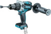
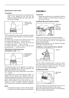
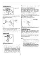
Adjustable depth rod 1. Depth rod 2. Clamp screw 1 2 014821 The adjustable depth rod is used to drill holes of uniform depth. Loosen the clamp screw, set to desired position, then tighten the clamp screw. Hook 1. Groove 2. Hook 3. Screw First, slide the action mode change lever so that it points to the marking. The adjusting ring can be aligned in any torque levels for this operation. Be sure to use a tungsten-carbide tipped bit. Position the bit at the desired location for the hole, then pull the switch trigger. Do not force the tool. Light pressure gives best results. Keep the tool in position and prevent it from slipping away from the hole. Do not apply more pressure when the hole becomes clogged with chips or particles. Instead, run the tool at an idle, then remove the bit partially from the hole. By repeating this several times, the hole will be cleaned out and normal drilling may be resumed. Blow-out bulb (optional accessory) 1. Blow-out bulb 1 1 2 3 014701 The hook is convenient for temporarily hanging the tool. This can be installed on either side of the tool. To install the hook, insert it into a groove in the tool housing on either side and then secure it with a screw. To remove, loosen the screw and then take it out. OPERATION 014702 Hammer drilling operation CAUTION: • There is a tremendous and sudden twisting force exerted on the tool/bit at the time of hole breakthrough, when the hole becomes clogged with chips and particles, or when striking reinforcing rods embedded in the concrete. Always use the side grip (auxiliary handle) and firmly hold the tool by both side grip and switch handle during operations. Failure to do so may result in the loss of control of the tool and potentially severe injury. 002449 After drilling the hole, use the blow-out bulb to clean the dust out of the hole. Screwdriving operation First, slide the action mode change lever so that it points to the marking. Adjust the adjusting ring to the proper torque level for your work. Then proceed as follows. Place the point of the driver bit in the screw head and apply pressure to the tool. Start the tool slowly and then increase the speed gradually. Release the switch trigger as soon as the clutch cuts in. NOTE: • Make sure that the driver bit is inserted straight in the screw head, or the screw and/or bit may be damaged. • When driving wood screw, predrill a pilot hole 2/3 the diameter of the screw. It makes driving easier and prevents splitting of the workpiece. • If the tool is operated continuously until the battery cartridge has discharged, allow the tool to rest for 15 minutes before proceeding with a fresh battery. 8
-
 1
1 -
2
-
 3
3 -
 4
4 -
 5
5 -
 6
6 -
 7
7 -
 8
8 -
 9
9 -
 10
10 -
 11
11 -
 12
12 -
 13
13 -
14
-
15
-
16
-
17
-
18
-
19
-
20
-
21
-
22
-
23
-
24
-
25
-
26
-
27
-
28
-
29
-
30
-
31
-
32
 |
 |
