Marantz SM-17SA Specifications - Page 4
Connection of speaker systems, CONNECTIONS - stereo amp
 |
View all Marantz SM-17SA manuals
Add to My Manuals
Save this manual to your list of manuals |
Page 4 highlights
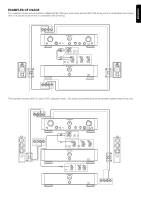
8 ENGLISH ENGLISH CONNECTIONS The connection method illustrated below is used when the SM-17SA is being used as a stereo power amp. For details on other connection methods, refer to the examples on the following page. MRANTZ PM-17SA Integrated-amp or other pre-amp INPUT SELECTOR CD PHONO LINE 1 LINE 2 LINE 3 PHONES CD-R TAPE CD-R REC SELECTOR CD TAPE LINE 1 COPY LINE 2 LINE 3 PHONO SPEAKERS ON OFF TEMP POWER BASS 0 2 2 4 4 - 6 6 + (dB) TREBLE 0 2 2 4 4 - 6 6 + (dB) VOLUME 20 27 15 35 13 43 10 58 BALANCE (-dB) 4 0 SOURCE DIRECT LEFT RIGHT ON OFF To pre output Speaker system Connect the right channel speaker system to the R output terminals and the left channel speaker system to the L output terminals. L R Set NORMAL position L R+ L+ ATT R R- L- 0 - 6 (dB) NORMAL INPUT BTL 2 L BTL OUT R L BTL SPEAKERS IMPEDANCE L&R : 4 OHMS BTL : 8 OHMS SPEAKERS SERIAL NO. 1.0A 120W MAX TOTAL 1.0A 120W MAX SWITCHED UNSWITCHED 120V 60HZ AC OUTLETS AC IN CONNECTIONS OF AMPLIFIER Connect the output jacks of your pre amplifier to the INPUT jacks To AC power outlet Connection of speaker systems Each of the speaker systems connected to this unit should have a impedance between 4 and 16 ohm. Connecting a speaker system with a lower impedance than 4 ohm may activate the protection circuitry during sound reproduction. The output terminals are provided with the positive ( :Red) and negative ( : White) polarity, and the input terminal of each speaker system also has the polarity ( and ). Be sure to connect the terminals with the identical polarity. Caution: If you will be using two speaker systems, or you will be using the SM-17SA in BTL mode, use speaker systems that have an impedance of at least 8 ohm. If you connect a speaker system that has an impedance of less than 8 ohm, the SM-17SA's protective circuitry may be worked, making the amplifier incapable of normal stereo playback. Connection of speaker cord Strip coating from extermity. Speaker cord Twist conductors. Turn counterclockwise to loosen. Insert conductors. Turn clockwise to tighten. 2
-
 1
1 -
 2
2 -
 3
3 -
 4
4 -
 5
5 -
 6
6
 |
 |
