Marantz SR5009 Instruction Manual in English - Page 14
INPUT SELECTOR knob, Headphones jack PHONES - no sound
 |
View all Marantz SR5009 manuals
Add to My Manuals
Save this manual to your list of manuals |
Page 14 highlights
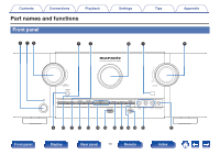
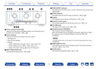
Contents Connections Playback qwe rt yu i . o Q0Q1 A Power operation button (X) Used to turn the power of the MAIN ZONE (room where this unit is located) on/off (standby). (v p. 58) B Power indicator This is lit as follows according to the power status: 0 Off: Power on 0 Red: Normal standby 0 Orange: 0 When "HDMI Pass Through" (v p. 166) is set to "On" 0 When "HDMI Control" (v p. 166) is set to "On" 0 When "IP Control" (v p. 200) is set to "Always On" C INPUT SELECTOR knob This selects the input source. (v p. 58) Settings Tips Appendix D PURE DIRECT indicator This lights when the "Pure Direct" mode is selected as the sound mode. (v p. 120) E M-DAX indicator This lights when the M-DAX mode is selected. (v p. 156) F Display This displays various pieces of information. (v p. 16) G Remote control sensor This receives signals from the remote control unit. (v p. 8) H VOLUME knob This adjusts the volume level. (v p. 59) I Headphones jack (PHONES) This is used to connect headphones. When the headphones are plugged into this jack, audio will no longer be output from the connected speakers or from the PRE OUT connectors. NOTE To prevent hearing loss, do not raise the volume level excessively when using headphones. J PURE DIRECT button This switches the sound mode between Direct, Pure Direct and Auto surround. (v p. 120, 121) K M-DAX button This switches the M-DAX mode. (v p. 156) Front panel Display Rear panel 14 Remote Index
-
 1
1 -
2
-
3
-
4
-
5
-
6
-
7
-
8
-
 9
9 -
 10
10 -
 11
11 -
 12
12 -
 13
13 -
 14
14 -
 15
15 -
 16
16 -
 17
17 -
 18
18 -
 19
19 -
20
-
21
-
22
-
23
-
24
-
25
-
26
-
27
-
28
-
29
-
30
-
31
-
32
-
33
-
34
-
35
-
36
-
37
-
38
-
39
-
40
-
41
-
42
-
43
-
44
-
45
-
46
-
47
-
48
-
49
-
50
-
51
-
52
-
53
-
54
-
55
-
56
-
57
-
58
-
59
-
60
-
61
-
62
-
63
-
64
-
65
-
66
-
67
-
68
-
69
-
70
-
71
-
72
-
73
-
74
-
75
-
76
-
77
-
78
-
79
-
80
-
81
-
82
-
83
-
84
-
85
-
86
-
87
-
88
-
89
-
90
-
91
-
92
-
93
-
94
-
95
-
96
-
97
-
98
-
99
-
100
-
101
-
102
-
103
-
104
-
105
-
106
-
107
-
108
-
109
-
110
-
111
-
112
-
113
-
114
-
115
-
116
-
117
-
118
-
119
-
120
-
121
-
122
-
123
-
124
-
125
-
126
-
127
-
128
-
129
-
130
-
131
-
132
-
133
-
134
-
135
-
136
-
137
-
138
-
139
-
140
-
141
-
142
-
143
-
144
-
145
-
146
-
147
-
148
-
149
-
150
-
151
-
152
-
153
-
154
-
155
-
156
-
157
-
158
-
159
-
160
-
161
-
162
-
163
-
164
-
165
-
166
-
167
-
168
-
169
-
170
-
171
-
172
-
173
-
174
-
175
-
176
-
177
-
178
-
179
-
180
-
181
-
182
-
183
-
184
-
185
-
186
-
187
-
188
-
189
-
190
-
191
-
192
-
193
-
194
-
195
-
196
-
197
-
198
-
199
-
200
-
201
-
202
-
203
-
204
-
205
-
206
-
207
-
208
-
209
-
210
-
211
-
212
-
213
-
214
-
215
-
216
-
217
-
218
-
219
-
220
-
221
-
222
-
223
-
224
-
225
-
226
-
227
-
228
-
229
-
230
-
231
-
232
-
233
-
234
-
235
-
236
-
237
-
238
-
239
-
240
-
241
-
242
-
243
-
244
-
245
-
246
-
247
-
248
-
249
-
250
-
251
-
252
-
253
-
254
-
255
-
256
-
257
-
258
-
259
-
260
-
261
-
262
-
263
-
264
-
265
-
266
-
267
-
268
-
269
-
270
-
271
-
272
-
273
-
274
-
275
-
276
-
277
 |
 |
