Maytag M1TXEMMWB User Instructions - Page 5
Refrigerator Doors
 |
UPC - 883049155289
View all Maytag M1TXEMMWB manuals
Add to My Manuals
Save this manual to your list of manuals |
Page 5 highlights
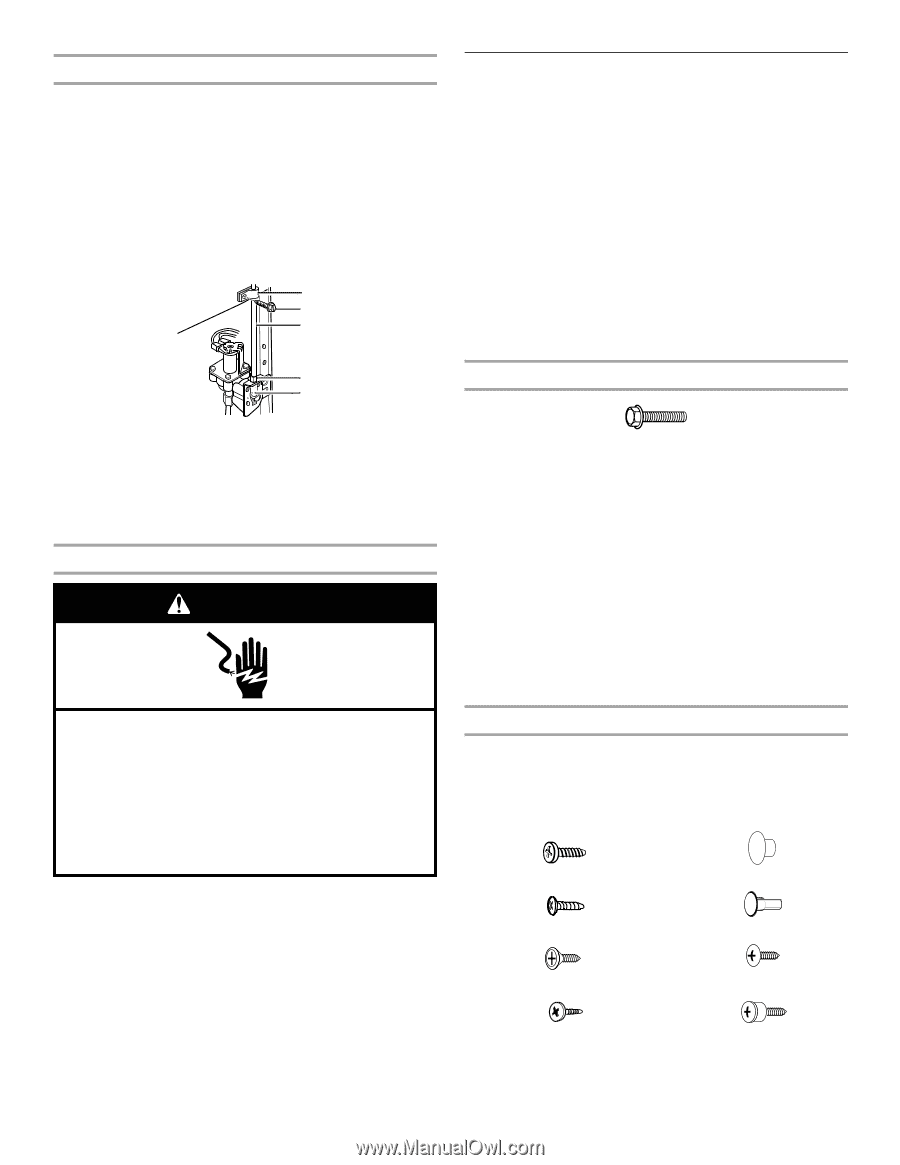
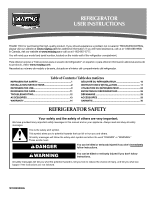
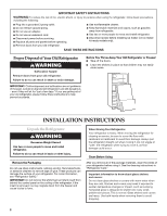
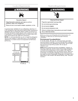
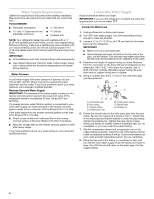
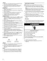
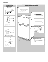
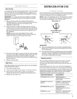
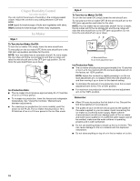
Connect to Refrigerator 1. Unplug refrigerator or disconnect power. 2. Attach the copper tube to the valve inlet using a compression nut and sleeve as shown. Tighten the compression nut. Do not overtighten. 3. Use the tube clamp on the back of the refrigerator to secure the tubing to the refrigerator as shown. This will help avoid damage to the tubing when the refrigerator is pushed back against the wall. 4. Turn shutoff valve ON. 5. Check for leaks. Tighten any connections (including connections at the valve) or nuts that leak. A B C D E A. Tube clamp B. Tube clamp screw C. Copper tubing D. Compression nut E. Valve inlet 6. The ice maker is equipped with a built-in water strainer. If your water conditions require a second water strainer, install it in the ¹⁄₄" (6.35 mm) water line at either tube connection. Obtain a water strainer from your nearest appliance dealer. Complete the Installation WARNING Electrical Shock Hazard Plug into a grounded 3 prong outlet. Do not remove ground prong. Do not use an adapter. Do not use an extension cord. Failure to follow these instructions can result in death, fire, or electrical shock. 1. Plug into a grounded 3 prong outlet. NOTE: Allow 24 hours to produce the first batch of ice. Discard the first three batches of ice produced. Allow 3 days to completely fill ice container. Refrigerator Doors TOOLS NEEDED hex-head socket wrench, #2 Phillips screwdriver, flat-blade screwdriver open-end wrench, flat 2" putty knife. IMPORTANT: ■ Unplug refrigerator or disconnect power. ■ Remove food and any adjustable door or utility bins from doors. ■ If you only want to remove and replace the doors, see "Remove Doors and Hinges" and "Replace Doors and Hinges." ■ Depending on your model, you have either standard doors or contour doors. If you are going to reverse the door swing, follow the instructions for the appropriate door style. ■ All graphics referenced in the following instructions are included later in this section after "Final Steps." Remove Doors and Hinges Hex-head hinge screw 1. Unplug refrigerator or disconnect power. 2. Open refrigerator door and remove base grille from the bottom front of the refrigerator. See Base Grille graphic. 3. Close the refrigerator door and keep both doors closed until you are ready to lift them free from the cabinet. NOTE: Provide additional support for the doors while the hinges are being moved. Do not depend on the door magnets to hold the doors in place while you are working. 4. Remove the parts for the top hinge as shown in Top Hinge graphic. Lift the freezer door free from the cabinet. 5. Remove the parts for the center hinge as shown in the Center Hinge graphic. Lift the refrigerator door free from the cabinet. 6. Remove the parts for the bottom hinge as shown in the Bottom Hinge graphic. Reverse Doors (optional) IMPORTANT: If you want to reverse your doors so that they open in the opposite direction, follow these steps. If you are not reversing the doors, see "Replace Doors and Hinges." Standard Doors Door Stop Screw Door Handle Sealing Screw Door Hinge Hole Plug Cabinet Hinge Hole Plug Flat-Head Handle Screw Round-Head Handle Screw Door Handle Seal Screw Front Shoulder Handle Screw 5
-
 1
1 -
 2
2 -
 3
3 -
 4
4 -
 5
5 -
 6
6 -
 7
7 -
 8
8 -
 9
9 -
 10
10 -
 11
11 -
12
-
13
-
14
-
15
-
16
-
17
-
18
-
19
-
20
-
21
-
22
-
23
-
24
-
25
-
26
-
27
-
28
-
29
-
30
-
31
-
32
 |
 |