Maytag MEC4430WB Installation Instructions - Page 4
Installation Instructions
 |
UPC - 883049184692
View all Maytag MEC4430WB manuals
Add to My Manuals
Save this manual to your list of manuals |
Page 4 highlights
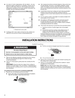
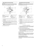
■ A 4-wire or 3-wire, single phase, 240 volt, 60 Hz., AC only electrical supply is required on a separate, 40-amp circuit, fused on both sides of the line. The model/serial number rating plate is located on the metal cabinet underneath the cooktop. See the following illustration. A A. Model/serial number plate ■ Cooktops with 3-wire cable coming from the cooktop are rated 240 volt and do not have a neutral (white) wire. ■ The cooktop should be connected directly to the junction box through flexible, armored or nonmetallic sheathed, copper cable. The flexible, armored cable extending from the fuse box or circuit breaker box should be connected directly to the junction box. ■ Locate the junction box to allow as much slack as possible between the junction box and the cooktop so that the cooktop can be moved if servicing becomes necessary in the future. ■ Do not cut the conduit. The length of conduit provided is for serviceability of the cooktop. ■ A UL listed or CSA approved conduit connector must be provided at each end of the power supply cable (at the cooktop and at the junction box). A listed conduit connector is already provided at the cooktop. ■ If the house has aluminum wiring follow the procedure below: 1. Connect a section of solid copper wire to the pigtail leads. 2. Connect the aluminum wiring to the added section of copper wire using special connectors and/or tools designed and UL listed for joining copper to aluminum. Follow the electrical connector manufacturer's recommended procedure. Aluminum/copper connection must conform with local codes and industry accepted wiring practices. INSTALLATION INSTRUCTIONS WARNING Install Cooktop ■ Pull the coil element straight away from the receptacle. Excessive Weight Hazard Use two or more people to move and install cooktop. Failure to do so can result in back or other injury. 1. Remove the shipping materials and tape from the cooktop. Remove the hardware package from inside the bag containing literature. 2. Using 2 or more people, gently place the cooktop into the cutout. IMPORTANT: Check that the front edge of the cooktop is parallel to the front edge of the countertop. If repositioning is needed, lift entire cooktop up from cutout to avoid scratching the countertop. If cooktop is to be secured to countertop (optional): 1. Remove the coil elements and burner bowls. ■ Push in the edge of coil element toward the receptacle. Then lift it enough to clear the burner bowl. ■ Lift out the burner bowl. 2. Remove the 4 screws from inside each element opening and lift cooktop from cooktop base. 3. Using 2 or more people, gently place the cooktop in cutout and determine final location. NOTE: Make sure that the front edge of the cooktop is parallel to the front edge of the countertop. If repositioning is needed, lift entire cooktop up from cutout to avoid scratching the countertop. 4
-
 1
1 -
 2
2 -
 3
3 -
 4
4 -
 5
5 -
 6
6 -
 7
7 -
 8
8 -
 9
9 -
 10
10 -
11
-
12
-
13
-
14
-
15
-
16
 |
 |
