Maytag MEC7430WB Installation Instructions - Page 2
Installation Requirements - installation instructions
 |
View all Maytag MEC7430WB manuals
Add to My Manuals
Save this manual to your list of manuals |
Page 2 highlights
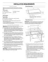
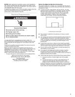
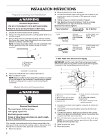
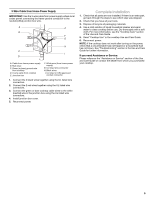
INSTALLATION REQUIREMENTS Tools and Parts Gather the required tools and parts before starting installation. Read and follow the instructions provided with any tools listed here. Tools needed ■ Tape measure ■ Marker or pencil ■ ¼" (6.35 mm) nut driver ■ Pliers ■ Level Parts supplied ■ Foam strip Parts needed ■ A UL listed or CSA approved conduit connector ■ UL listed wire connectors Check local codes. Check existing electrical supply. See "Electrical Requirements." It is recommended that all electrical connections be made by a licensed, qualified electrical installer. Location Requirements IMPORTANT: Observe all governing codes and ordinances. When installing cooktop, use minimum dimensions given. ■ To eliminate the risk of burns or fire by reaching over the heated surface units, cabinet storage space located above the surface units should be avoided. If cabinet storage is to be provided, the risk can be reduced by installing a range hood that projects horizontally a minimum of 5" (12.7 cm) beyond the bottom of the cabinets. ■ The cooktop must be a specified cooktop that is approved to be installed either alone or over an undercounter built-in oven. Check the cooktop base for an approved installation label. If you do not find this label, contact your dealer to confirm that your cooktop is approved. ■ Ovens approved for this type of installation will have an approval label located on the top of the oven. If you do not find this label, contact your dealer to confirm that your oven is approved. Refer to oven manufacturer's Installation Instructions for approval for built-in undercounter use and proper cutout dimensions. ■ The cooktop should be installed away from strong draft areas, such as windows, doors, fans or strong heating vents. The cooktop should be located for convenient use in the kitchen. ■ Use the countertop opening dimensions that are given with these Installation Instructions. Given dimensions are minimum clearances and provide 0" (0 cm) clearance. ■ Grounded electrical supply is required. See "Electrical Requirements" section. IMPORTANT: To avoid damage, check with your builder or cabinet supplier to make sure that the materials used will not discolor, delaminate or sustain other damage. Product Dimensions B A C A. 21½" (54.6 cm) B. 30" (76.2 cm) models - 30" (76.2 cm) 36" (91.4 cm) models - 35 89.7 cm) C. 3¾" (9.5 cm) Cabinet Dimensions IMPORTANT: If installing a range hood or microwave hood combination above the cooktop, follow the range hood or microwave hood combination installation instructions for dimensional clearances above the cooktop surface. A D C B F G E H H J I A. 30" (76.2 cm) on 30" models; 36" (91.4 cm) on 36" models B. Combustible area above countertop (shown by dashed box above) C. 30" (76.2 cm) minimum clearance between top of cooktop platform and bottom of unprotected wood or metal cabinet (24" [61 cm] minimum clearance if bottom of wood or metal cabinet is protected by not less than ¹⁄₄" [0.6 cm] flame retardant millboard covered with not less than No. 28 MSG sheet steel, 0.015" [0.04 cm] stainless steel, or 0.024" [0.06 cm] aluminum or 0.020" [0.05 cm] copper) D. 13" (33 cm) recommended upper cabinet depth E. 2¹⁄₈" (5.4 cm) F. 20 51.75 +/- 0.16 cm) G. 18" (45.7 cm) minimum clearance from upper cabinet to countertop within minimum horizontal clearances to cooktop H. Junction box or outlet: 6" (15.2 cm) minimum from top of counterop; 7" (17.8 cm) maximum from right side of cabinet I. 29 73.8 +/- 0.16 cm) on 30" (76.2 cm) models 34 87.8 +/- 0.16 cm) on 36" (91.4 cm) models J. 1" (2.5 cm) minimum distance to nearest left and right side combustible surface above cooktop 2
-
 1
1 -
 2
2 -
 3
3 -
 4
4 -
 5
5 -
 6
6 -
 7
7 -
 8
8 -
9
-
10
-
11
-
12
-
13
-
14
-
15
-
16
 |
 |
