Maytag MED3500FW Dimension Guide - Page 1
Maytag MED3500FW Manual
 |
View all Maytag MED3500FW manuals
Add to My Manuals
Save this manual to your list of manuals |
Page 1 highlights
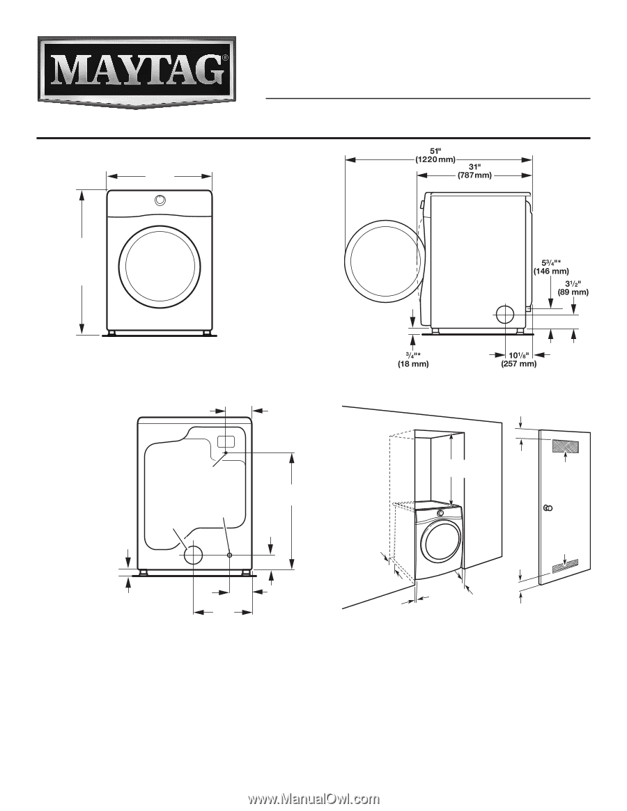
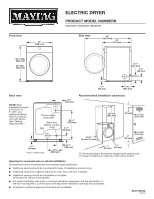
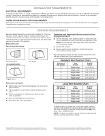
Front view 27" (686 mm) 383/4" Min. (984 mm) 39" Max. (990 mm) ELECTRIC DRYER PRODUCT MODEL NUMBERS MED3500F, MED5500F, MED8200F Side view Back view NOTE: Most installations require a minimum of 5" (127 mm) clearance behind dryer for exhaust vent with elbow. See "Venting Requirements." 61/2" (165 mm) Recommended installation clearances Power supply cord/cable Water inlet (Steam models Vent only) 297/8"* (759 mm) 31/2"* (89 mm) 5" (102"7-5m"*m) (0 mm-127 mm) 18" min. (457 mm) 3" (76 mm) 48 in.2 min. (310 cm2) 24 in.2 min. (155 cm2) 3" (76 mm) 3/4"* (18 mm) *Approx. measurement. 143/8" (365 mm) 61/8"* (156 mm) 1" (25 mm) 1" (25 mm) *0" (0 mm) spacing is allowed for straight-back venting only. For steam models only, inlet hose must not be kinked. Spacing for recessed area or closet installation All dimensions show recommended and minimum spacing allowed. ■■ Additional spacing should be considered for ease of installation and servicing. ■■ Additional clearances might be required for wall, door, and floor moldings. ■■ Additional spacing should be considered on all sides of the dryer to reduce noise transfer. ■■ For closet installation with a door, minimum ventilation openings in the top and bottom of the door are required. Louvered doors with equivalent ventilation openings are acceptable. ■■ Companion appliance spacing should also be considered. W10775223A 12/2015
-
 1
1 -
 2
2
 |
 |