Maytag MED5430MW Owners Manual - Page 17
Plan Vent System, Determine vent length and elbows needed for best
 |
View all Maytag MED5430MW manuals
Add to My Manuals
Save this manual to your list of manuals |
Page 17 highlights
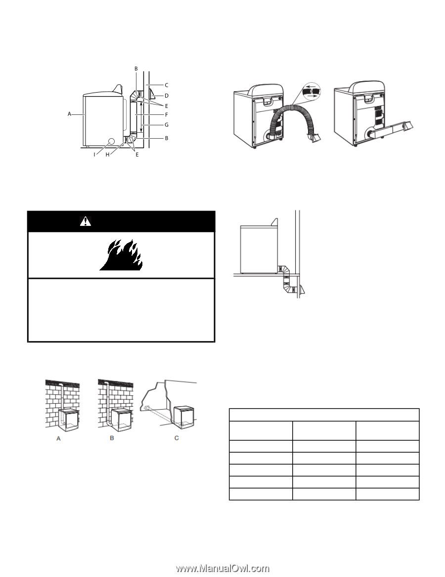
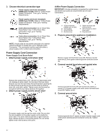
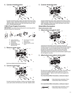
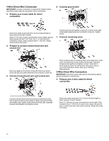
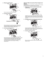
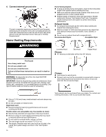
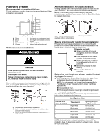
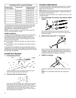
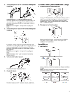
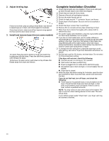
Plan Vent System Recommended exhaust installations: Typical installations vent the dryer from the rear of the dryer. Other installations are possible. Alternate installations for close clearances Venting systems come in many varieties. Select the type best for your installation. Two close-clearance installations are shown. NOTE: The following kits for close-clearance alternate installations are available for purchase. Refer to Quick Start Guide for contact information. A. Dryer B. Elbow C. Wall D. Exhaust hood E. Clamps F. Rigid metal or flexible metal vent G. Vent length necessary to connect elbows H. Exhaust outlet I. Optional side exhaust outlet Optional exhaust installations: WARNING Fire Hazard Cover unused exhaust holes with a manufacturer's exhaust cover kit. Contact your local dealer. Failure to follow these instructions can result in death, fire, electrical shock, or serious injury. Some models can be converted to exhaust out the right side, left side, or through the bottom. If you prefer, you may contact your local dealer to have the dryer converted. A. Standard rear offset exhaust installation B. Left- or right-side exhaust installation (available only on select 27"-wide models). C. Bottom exhaust installation (available only on select 27"- wide models). Over-The-Top installation (also available with one offset elbow) Periscope installation Special provisions for mobile home installations: Exhaust vent must be securely fastened to a noncombustible portion of the mobile home and must not terminate beneath the mobile home. Terminate exhaust vent outside. Determine vent path: � Select route that will provide straightest and most direct path outdoors. � Plan installation to use fewest number of elbows and turns. � When using elbows or making turns, allow as much room as possible. � Bend vent gradually to avoid kinking. � Use as few 90° turns as possible. Determine vent length and elbows needed for best drying performance: � Use following "Vent System Chart" to determine type of vent material and hood combinations acceptable to use. NOTE: Do not use vent runs longer than those specified in "Vent System Chart." Exhaust systems longer than those specified will: � Shorten life of dryer. � Reduce performance, resulting in longer drying times and increased energy usage. The "Vent System Chart" provides venting requirements that will help achieve best drying performance. Vent System Chart Number of 90° turns or elbows Type of vent Box/louvered or Angled hoods 0 Rigid metal 64 ft (20 m) 1 Rigid metal 54 ft (16.5 m) 2 Rigid metal 44 ft (13.4 m) 3 Rigid metal 35 ft (10.7 m) 4 Rigid metal 27 ft (8.2 m) NOTE: Side and bottom exhaust installations have a 90º turn inside the dryer. To determine maximum exhaust length, add one 90º turn to the chart. 17
-
 1
1 -
2
-
3
-
4
-
5
-
6
-
7
-
8
-
9
-
10
-
11
-
 12
12 -
 13
13 -
 14
14 -
 15
15 -
 16
16 -
 17
17 -
 18
18 -
 19
19 -
 20
20 -
 21
21 -
 22
22 -
23
-
24
-
25
-
26
-
27
-
28
-
29
-
30
-
31
-
32
-
33
-
34
-
35
-
36
-
37
-
38
-
39
-
40
-
41
-
42
 |
 |