Maytag MED5500FC Dimension Guide - Page 2
Venting Requirements, Installation Requirements
 |
View all Maytag MED5500FC manuals
Add to My Manuals
Save this manual to your list of manuals |
Page 2 highlights
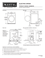
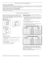
INSTALLATION REQUIREMENTS ELECTRICAL REQUIREMENTS To supply the required 3- or 4-wire, single phase, 120/240 volt, 60 Hz, AC only electrical supply (or 3- or 4-wire, 120/208 volt electrical supply, if specified on the serial/rating plate) on a separate 30-amp circuit, fused on both sides of the line. Connect to an individual branch circuit. Do not have a fuse in the neutral or grounding circuit. WATER (STEAM MODELS ONLY) REQUIREMENTS The dryer must be connected to the cold water faucet using new inlet hoses (not supplied). Do not use old hoses. Do not overtighten. Damage to the coupling can result. VENTING REQUIREMENTS Exhaust venting: Exhaust your dryer to the outside. 4" (102 mm) diameter vent is required. Rigid or flexible metal exhaust vent must be used. Do not use plastic or metal foil vet. Exhaust hood must be at least 12" (305 mm) from the ground or any object that may be in the path of the exhaust. Exhaust hoods: Recommended styles: Determine vent length and elbows needed for best drying performance: ■■ Use the following "Vent System Charts" to determine type of vent material and hood combinations acceptable to use. NOTE: Do not use vent runs longer than those specified in "Vent System Charts." ■■ Shorten life of dryer. ■■ Reduce performance, resulting in longer drying times and increased energy usage. The "Vent System Charts" provide venting requirements that will help achieve best drying performance. Louvered Hood Acceptable style: Box Hood Angled Hood Standard Vent System Chart Number of 90° elbows Type of vent Angled hoods 0 Rigid metal 64 ft. (20 m) 1 Rigid metal 54 ft. (16.5 m) 2 Rigid metal 44 ft. (13.4 m) 3 Rigid metal 35 ft. (10.7 m) 4 Rigid metal 27 ft. (8.2 m) Determine vent path: ■■ Select route that will provide straightest and most direct path outdoors. ■■ Plan installation to use fewest number of elbows and turns. ■■ When using elbows or making turns, allow as much room as possible. ■■ Bend vent gradually to avoid kinking. ■■ Use as few 90° turns as possible. Long Vent System Chart Number of 90° elbows Type of vent Angled hoods 0 Rigid metal 160 ft. (48.8 m) 1 Rigid metal 150 ft. (45.7 m) 2 Rigid metal 140 ft. (42.7 m) 3 Rigid metal 130 ft. (39.6 m) 4 Rigid metal 120 ft. (36.6 m) To determine if your model has a long vent system, refer to the type code located on the serial number plate in the inner door well. Example: An electric model would be DALV (Long Vent) - ELE - XXXXXXX-XXX. NOTE: For long vent systems, use of box/louvered hoods will improve venting, regardless of length. Because Whirlpool Corporation policy includes a continuous commitment to improve our products, we reserve the right to change materials and specifications without notice. Dimensions are for planning purposes only. For complete details, see Installation Instructions packed with product. Specifications subject to change without notice.
-
 1
1 -
 2
2
 |
 |