Maytag MED6230RHW Owners Manual - Page 9
Install Leveling Legs, Make Electrical Connection, U.s.a. Only
 |
View all Maytag MED6230RHW manuals
Add to My Manuals
Save this manual to your list of manuals |
Page 9 highlights
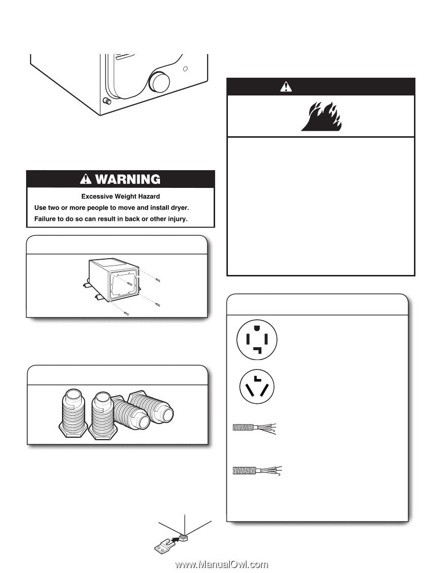
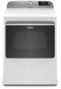
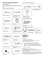
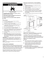
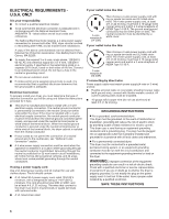
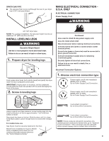
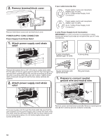
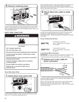
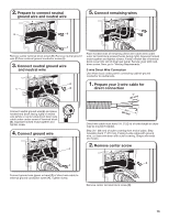
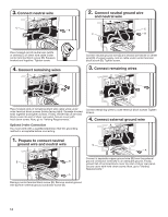
DRYER GAS PIPE ■■ The gas pipe that comes out through the rear of your dryer has a 3/8" male pipe thread. MAKE ELECTRICAL CONNECTION U.S.A. ONLY ELECTRICAL CONNECTION Power Supply Cord WARNING 3/8" NPT dryer pipe NOTE: For a garage installation, the gas pipe height must be an additional 18" (460 mm) from the floor. INSTALL LEVELING LEGS 1. Prepare dryer for leveling legs Firmly grasp dryer body (not console panel) and gently lay dryer down on back cardboard corner posts. IMPORTANT: If laying dryer on its back, use the cardboard corner posts the dryer was packed with to avoid damaging the back of the dryer. 2. Screw in leveling legs Fire Hazard Use a new UL listed 30 amp power supply cord. Use a UL listed strain relief. Disconnect power before making electrical connections. Connect neutral wire (white or center wire) to center terminal (silver). Ground wire (green or bare wire) must be connected to green ground connector. Connect remaining 2 supply wires to remaining 2 terminals (gold). Securely tighten all electrical connections. Failure to do so can result in death, fire, or electrical shock. Electrical Connection Options 1. Choose electrical connection type Power supply cord 4-wire receptacle (NEMA Type 14-30R): Go to Power Supply Cord Connection. Power supply cord 3-wire receptacle (NEMA Type 10-30R): Go to Power Supply Cord Connection. Using a wrench and tape measure, screw leveling legs into leg holes until bottom of foot is approximately 1" (25 mm) from bottom of dryer. Now stand the dryer on its feet. Slide the dryer until it is close to its final location. Leave enough room to connect the exhaust vent. For mobile home use Gas dryers must be securely fastened to the floor. Mobile home installations require a Mobile Home Installation Hold-down Kit. For ordering information please reference the "Quick Reference Guide." 4-wire direct connection: Go to Direct Wire Connection. 3-wire direct connection: Go to Direct Wire Connection. NOTE: If local codes do not permit connection of a cabinet-ground conductor to neutral wire, go to "Optional 3-wire connection." This connection may be used with either a power supply cord or a direct wire connection. 9
-
 1
1 -
2
-
3
-
 4
4 -
 5
5 -
 6
6 -
 7
7 -
 8
8 -
 9
9 -
 10
10 -
 11
11 -
 12
12 -
 13
13 -
 14
14 -
15
-
16
-
17
-
18
-
19
-
20
-
21
-
22
-
23
-
24
-
25
-
26
-
27
-
28
-
29
-
30
-
31
-
32
-
33
-
34
-
35
-
36
-
37
-
38
-
39
-
40
-
41
-
42
-
43
-
44
-
45
-
46
-
47
-
48
-
49
-
50
-
51
-
52
-
53
-
54
-
55
-
56
-
57
-
58
-
59
-
60
-
61
-
62
-
63
-
64
-
65
-
66
-
67
-
68
-
69
-
70
-
71
-
72
-
73
-
74
-
75
-
76
-
77
-
78
-
79
-
80
-
81
-
82
-
83
-
84
-
85
-
86
-
87
-
88
 |
 |