Maytag MEDB850WQ Installation Guide - Page 15
Connect Inlet Hoses, Install Vent System - steam dryer
 |
UPC - 883049179254
View all Maytag MEDB850WQ manuals
Add to My Manuals
Save this manual to your list of manuals |
Page 15 highlights
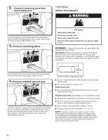
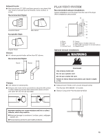
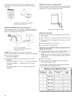
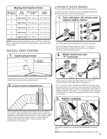
Maytag Vent System Chart Number of 90° elbows Type of vent Box/louvered hoods Angled hoods 0 Rigid metal 100 ft. (30.5 m) 94 ft. (28.7 m) 1 Rigid metal 90 ft. (27.4 m) 84 ft. (25.6 m) 2 Rigid metal 80 ft. (24.4 m) 74 ft. (22.6 m) 3 Rigid metal 71 ft. (21.6 m) 65 ft. (19.8 m) 4 Rigid metal 63 ft. (19.2 m) 57 ft. (17.4 m) NOTE: Bottom exhaust installations have a 90° turn inside the dryer. To determine maximum exhaust length, add one 90° turn to the charts. INStall VENT SYSTEM 1. Install exhaust hood 12" min. (305 mm) CONNECT INLET HOSES For non-steam models, skip to "Connect Vent" on page 16. The dryer must be connected to the cold water faucet using the new inlet hoses. Do not use old hoses. 1. Turn cold water off, remove and replace rubber washer Turn cold water faucet off and remove washer inlet hose. Check and see if rubber washer is in the "Y" connector. Remove old rubber washer from inlet hose and replace with new rubber washer provided. 2. Attach short hose and "Y" connector 12" min. (305 mm) Install exhaust hood and use caulking compound to seal exterior wall opening around exhaust hood. 2. Connect vent to exhaust hood Fig. A Fig. B If space permits, attach the brass female end of the "Y" connector to the cold water faucet. See figure A. If "Y" connector cannot be attached directly to the cold water faucet, the short hose must be used. See figure B. Attach short hose to cold water faucet. Screw on coupling by hand until it is seated on faucet. Then attach "Y" connector to brass male end of the short hose. Screw on coupling by hand until it is seated on connector. 3. Tighten couplings Vent must fit over the exhaust hood. Secure vent to exhaust hood with 4" (102 mm) clamp. Run vent to dryer location using straightest path possible. Avoid 90° turns. Use clamps to seal all joints. Do not use duct tape, screws, or other fastening devices that extend into interior of vent to secure vent, because they can catch lint. Using pliers, tighten the couplings with additional two-thirds turn. NOTE: Do not overtighten. Damage to the coupling can result. 15
-
 1
1 -
2
-
3
-
4
-
5
-
6
-
7
-
8
-
9
-
 10
10 -
 11
11 -
 12
12 -
 13
13 -
 14
14 -
 15
15 -
 16
16 -
 17
17 -
 18
18 -
 19
19 -
 20
20
 |
 |