Maytag MEDX700XW Dimension Guide - Page 1
Maytag MEDX700XW Manual
 |
View all Maytag MEDX700XW manuals
Add to My Manuals
Save this manual to your list of manuals |
Page 1 highlights
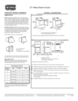
27" Wide Electric Dryer PRODUCT MODEL NUMBERS MEDX700X Electrical: This dryer requires a 3 or 4 wire, single phase, 120/240 volt, 60 Hz., AC only electrical supply (or 3 or 4 wire, 120/208 volt electrical supply, if specified on the serial/rating plate) on a separate 30-amp circuit, fused on both sides of the line. A time-delay fuse or circuit breaker is recommended. Connect to an individual branch circuit. Do not have a fuse in the neutral or grounding circuit. Exhaust venting: Exhaust your dryer to the outside. 4" (102 mm) diameter vent is required. Rigid or flexible metal exhaust vent must be used. Do not use plastic or metal foil vet. Exhaust hood must be at least 12" (305 mm) from the ground or any object that may be in the path of the exhaust. Hood styles: A & B are recommended. OVERALL DIMENSIONS Dryer dimensions 43 " (1092 mm) 23 ¾" (603 mm) 43 " (1092 mm) 13 ¾" (349 mm) *29 1/2" (749 mm) 27" (687 mm) A *29 1/2" (749 mm) 27" (687 mm) B A. Large opening side-swing door B. Wide opening hamper door The location must be large enough to allow the dryer door to open fully. A B A. Louvered hood B. Box hood C. Angled hood (acceptable) C The vent system chart provides venting requirments that will help to achieve the best drying performance. Vent system chart: NOTE: Side and bottom exhaust installations have a 90° turn inside the dryer. To determine maximum exhaust length, add one 90° turn to the chart. Vent System Chart Number of 90° turns or elbows Type of vent Box/louvered hoods Angled hoods 0 Rigid metal 64 ft. (20 m) 58 ft. (17.7 m) 1 Rigid metal 54 ft. (16.5 m) 48 ft. (14.6 m) 2 Rigid metal 44 ft. (13.4 m) 38 ft. (11.6 m) Select3the rouRteigtidhamt ewtailll pr3o5vfitd. e(10th.7ems)trai2g9htfte.s(8t.a8nmd) most direct path outdoors. Plan the installation to use th4e fewesRt inguidmmbeetraol f e2l7bfot.w(8s.2amnd) tur2n1s.ftU. (s6e.4tmhe) fewest 90° turns possible. Do not use vent runs longer than specified in vent length chart. Determine the number of elbows you will need. Minimum required spacing for recessed or closet installation 3"* 14" max.* (76 mm) (356 mm) 48 in.2* 18"* (310 cm ) 2 (457 mm) 1" (25 mm) 27" (686 mm) A 24 in2.* 2 (155 cm ) 1" 1"* 29¼" 5½"* (25 mm) (25 mm) (743 mm) (140 mm) B C A. Recessed area B. Side view - closet or confined area C. Closet door with vents *Additional spacing recommended 3"* (76 mm) The dimensions shown following are for the minimum spacing allowed. ■■ Additional spacing should be considered for ease of installation and servicing. ■■ Additional clearances might be required for wall, door, and floor moldings. ■■ Additional spacing of 1" (25 mm) on all sides of the dryer is recommended to reduce noise transfer. ■■ For closet installation, with a door, minimum ventilation openings in the top and bottom of the door are required. Louvered doors with equivalent ventilation openings are acceptable. ■■ Companion appliance spacing should also be considered. Because Whirlpool Corporation policy includes a continuous commitment to improve our products, we reserve the right to change materials and specifications without notice. Dimensions are for planning purposes only. For complete details, see Installation Instructions packed with product. Specifications subject to change without notice. Ref. W10115226B 01/2011
-
 1
1
 |
 |
