Maytag MER5875RAB Installation Manual
Maytag MER5875RAB - 30" Electric Range Manual
 |
View all Maytag MER5875RAB manuals
Add to My Manuals
Save this manual to your list of manuals |
Maytag MER5875RAB manual content summary:
- Maytag MER5875RAB | Installation Manual - Page 1
INSTRUCTIONS WITH THE APPLIANCE INSTALLATION MANUAL Electric 30-inch Wide Free-standing Range PLEASE KEEP THIS MANUAL FOR FUTURE REFERENCE THE MANUAL IS INTENDED TO ASSIST IN THE INITIAL INSTALLATION AND ADJUSTMENTS OF THE RANGE. SPECIAL WARNING Only qualified personnel should install or service - Maytag MER5875RAB | Installation Manual - Page 2
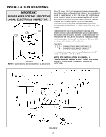
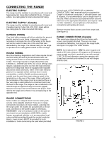
OF THE LOCAL ELECTRICAL INSPECTOR. 4 3 1 "A" 2 FIGURE 1 NOTE: Figure may not be representative of actual unit. "A" = 30 inches (76.2 cm cabinet storage is to be provided, the risk can be reduced by installing a range hood that projects horizontally a minimum of 5 inches (13 cm) beyond the bottom - Maytag MER5875RAB | Installation Manual - Page 3
of range tip-over exists if the appliance is not installed in accordance with the provided installation instructions. The proper use of this device minimizes the risk of TIP-OVER. In using this device the consumer must still observe the safety precautions as stated in the USE and CARE MANUAL and - Maytag MER5875RAB | Installation Manual - Page 4
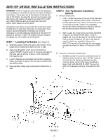
INSTRUCTIONS STEP 3 - Range Installation A. For safety considerations as well as optimum performance, adjust the range so it is level and to desired height prior to installing in cabinet opening. Levelness may be checked by placing a spirit level or a large pan of water on the cooktop or oven - Maytag MER5875RAB | Installation Manual - Page 5
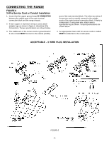
6 and 7). After installation, insure tightness of all electrical connections and replace all covers. Remove terminal block access cover from range back. (See figure 5). RANGE CONNECTIONS (Canada) This model was shipped direct from the factory with service cord (pigtail) attached. There are no - Maytag MER5875RAB | Installation Manual - Page 6
post of the main terminal connection block and the range chassis. 2. If bare copper or aluminum wiring is used, attach adapter lugs as shown in figure 6. (See Bare Wire Connection). Torque specifications are shown below. 3. The middle wire of the service cord or ground lead of 3-wire conduit MUST - Maytag MER5875RAB | Installation Manual - Page 7
plate. Conversion From 3-Wire To 4-Wire Service (Free-standing Model With 3-Wire Service Cord Attached). Disconnect range from power. Remove the access cover on back of range and remove the 3-wire service cord from the main terminal block. Follow instructions as outlined in figure 7 to connect the - Maytag MER5875RAB | Installation Manual - Page 8
EL APARATO MANUAL DE INSTALACIÓN Estufa eléctrica individual de 30 pulgadas (76.2 cm) de ancho CONSERVE ESTE MANUAL PARA REFERENCIA FUTURA EL MANUAL TIENE LA Título 24 CFR, Parte 3280 (anteriormente Federal Standard for Mobile Home Construction and Safety, Título 24 HUD, Parte 280)) o, cuando dichas - Maytag MER5875RAB | Installation Manual - Page 9
DE 120/208 VOLTIOS, 120/240 VOLTIOS AL RAS POR CADA CORDÓN CORRESPONDIENTE EN ESTA ÁREA "A" = 30 pulgadas (76.2 cm) espacio mínimo entre la parte superior de la superficie de cocinar y la parte inferior de un gabinete sin protección de madera o metal, o "A" = 24 pulgadas (61 cm) cuando menos cuando - Maytag MER5875RAB | Installation Manual - Page 10
reduce el riesgo de LADEO. Al usar este dispositivo el consumidor aun debe acatar las precauciones de seguridad que se dictan en el MANUAL DE USO Y CUIDADO y debe evitar utilizar las puertas del horno como banquillo. Las instrucciones de instalación se proporcionan para madera y cemento tanto en - Maytag MER5875RAB | Installation Manual - Page 11
superior principal o por el protector posterior o el asa de la puerta. Todas las estufas individuales con la parte superior de vidrio tienen la parte superior fija. La parte superior del serpentín se puede levantar. B. Alinee la estufa en su ubicación final y prepárela para deslizarla hacia atr - Maytag MER5875RAB | Installation Manual - Page 12
úrese de que todas las conexiones eléctricas estén bien ajustadas y coloque todas las cubiertas. Quite la cubierta de acceso del bloque terminal de la parte posterior de la estufa. (Vea la figura 5). CONEXIONES DE LA ESTUFA (en Canadá) Este modelo se embarcó directamente de fábrica con el cordón de - Maytag MER5875RAB | Installation Manual - Page 13
CONEXIÓN DE LA ESTUFA FIGURA 6 INSTALACIÓN DEL CORDÓN DE SERVICIO DE 3 CABLES O DEL CONDUCTOR 1. Verifique que la tira de conexión a tierra de cobre ESTÉ CONECTADA entre el poste medio del bloque de conexión del terminal principal y del bastidor de la estufa. 2. Si se usa alambrado desnudo de - Maytag MER5875RAB | Installation Manual - Page 14
Modelo individual con cordón sujeto de servicio de 3 cables) Desconecte la estufa de la energía eléctrica. Quite la cubierta de acceso en la parte posterior de la estufa y quite el cordón de servicio de 3 cables del bloque del terminal principal. Siga las instrucciones a continuación según se indica - Maytag MER5875RAB | Installation Manual - Page 15
INSTRUCTIONS AVEC L'APPAREIL MANUEL DE MISE EN SERVICE Cuisinière électrique amovible de 30 po (76,2 cm) VEUILLEZ CONSERVER CE MANUEL POUR RÉFÉRENCE ULTÉRIEURE CE MANUEL EST DESTINÉ À FACILITER LA MISE EN SERVICE ère est adjacente à des armoires pouvant supporter une température inférieure à 194°F - Maytag MER5875RAB | Installation Manual - Page 16
sont en matériau combustible. REMARQUE : DANS LE CAS D'UNE MISE EN SERVICE AU CANADA, UNE CUISINIÈRE AMOVIBLE NE DOIT PAS ÊTRE PLACÉE À ÉVOIR UNE PRISE ENCASTRÉE DE 120/208 V / 120/240 V PAR CORDON D'ALIMENTATION DANS CETTE ZONE A = 30 PO (76,2 CM) - 31 PO (78,7 CM) -- CANADA B = 3 1/4 PO (8,3 CM) - - Maytag MER5875RAB | Installation Manual - Page 17
cuisinière risque de basculer si elle n'est pas mise en place conformément aux instructions fournies. Si le support est utilisé correctement, il réduit le risque que la cuisinière ne BASCULE. Même si le support est utilisé correctement, le consommateur doit observer les précautions indiquées dans le - Maytag MER5875RAB | Installation Manual - Page 18
é. Remarque : Un dégagement minimum de 6 mm (1/4 po) est exigé entre la cuisinière et le pied de mise à niveau qui va s'insérer dans le support de stabilisation (voir figure 4). Attention : La cuisinière peut se trouver abîmée si elle est déplacée et soulevée par le dessus, à l'aide du dosseret ou - Maytag MER5875RAB | Installation Manual - Page 19
connaître la puissance raccordée totale (en kW). ALIMENTATION ÉLECTRIQUE (Canada) Lors de la mise en service, la cuisinière doit être installée conformément aux normes ACN STD.C22.1 de l'édition la plus , les véhicules de loisir ou dans toute -19- PLAQUE DE SUPPORT DE GAINE COUVERCLE D'ACCÈS FIGURE 5 - Maytag MER5875RAB | Installation Manual - Page 20
BORNIER -- 20 PO--LB CÂBLE AWG 10--14 8 4--6 COUPLE DE 20 PO--LB 25 PO--LB 35 PO--LB À UTILISER AVEC UNE GAINE. ENLEVER LE SUPPORT, RETOURNER ET FIXER À NOUVEAU AVEC LE PETIT TROU VISIBLE. INSTALLATION ALTERNATIVE PRISE ENCASTRÉE DANS LE MUR TOURNER LA PRISE DANS L'AUTRE SENS TEL QU'INDIQU - Maytag MER5875RAB | Installation Manual - Page 21
connecter le cordon d'alimentation à 3 fils du bornier. Suivre les instructions données à la figure 7 pour connecter le cordon à 4 PO--LB 35 PO--LB INSTALLATION ALTERNATIVE À UTILISER AVEC UNE GAINE. ENLEVER LE SUPPORT, RETOURNER ET FIXER À NOUVEAU AVEC LE PETIT TROU VISIBLE. PRISE ENCASTRÉE DANS
-
 1
1 -
 2
2 -
 3
3 -
 4
4 -
 5
5 -
 6
6 -
 7
7 -
8
-
9
-
10
-
11
-
12
-
13
-
14
-
15
-
16
-
17
-
18
-
19
-
20
-
21
 |
 |
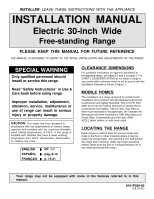
INSTALLER
: LEAVE THESE INSTRUCTIONS WITH THE APPLIANCE
INSTALLATION MANUAL
Electric 30-inch Wide
Free-standing Range
PLEASE KEEP THIS MANUAL FOR FUTURE REFERENCE
THE MANUAL IS INTENDED TO ASSIST IN THE INITIAL INSTALLATION AND ADJUSTMENTS OF THE RANGE.
SPECIAL WARNING
Only qualified personnel should
install or service this range.
Read °Safety Instructions± in Use &
Care book before using range.
Improper installation, adjustment,
alteration, service, maintenance or
use of range can result in serious
injury or property damage.
CLEARANCE
DIMENSIONS
For complete information in regard to installation of
freestanding range, see figures 1 and 2 on page 2. For
SAFETY CONSIDERATIONS do not install a range in
any combustible cabinetry which is not in accord with the
installation clearances shown in figure 1.
MOBILE
HOMES
The installation of a range designed for mobile home
installation must conform with the Manufactured Home
Construction and Safety Standard, Title 24 CFR, Part
3280 (formerly the Federal Standard for Mobile Home
Construction and Safety, Title 24 HUD, Part 280) or,
when such standard is not applicable, the Standard for
Manufactured Home Installations 1982 (Manufactured
Home Sites, Communities and Set-Ups), ANSI
A225.1-latest edition, or with local codes.
LOCATING THE
RANGE
Place range in a well lit area. Do not set range over
holes in the floor or other locations where it may be
subject to strong drafts. Any opening in the wall behind
the range and in the floor under the range should be
sealed. Make sure the flow of cooling/ventilation air is
not obstructed below the range.
CAUTION:
This range has been designed in
accordance with the requirements of various safety
agencies and complies with the maximum allowable
wood cabinet temperatures of 194
±
F. If this range is
installed with cabinets that have a lower working
temperature than 194
±
F, discoloration, delamination
or melting may occur.
8101P506-60
(08-03-01)
Your range may not be equipped with some of the features referred to in this
manual.
ENGLISH
’
PP. 1-7
ESPA²OL
’
pÆg. 8-14
FRAN˙AIS
’
p. 15-21